TAGGED: ale, fluidstructureinteraction
-
-
July 14, 2023 at 7:39 pm
Caleb Wood
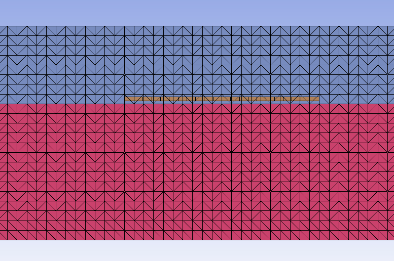
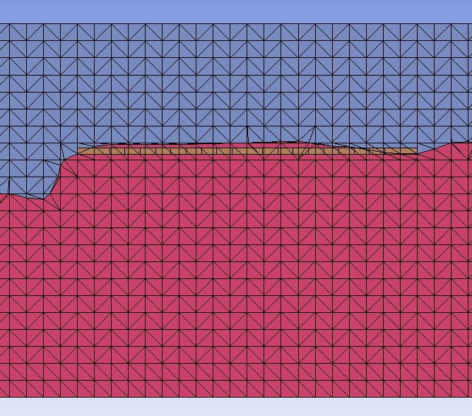
SubscriberHello, I am modelling a fluid-structure interation problem where water modelled with ALE elements impacts a rigid plate. The model consists of water and air elements both modelled using an ALE formulation and a rigid plate constructed of solid elements. The rigid plate sits just above the air-water interface so that water only interacts with it when a large wave is produced. My results are coming out close to expected, however when I watch the simulation in the d3plot file, it is observed that after a wave propagates past the plate, the water does not go back to its still water level and instead creates a "hump". Any insight on this issue would be greatly appreciated.
-
July 18, 2023 at 3:58 pm
Ian Do
Ansys EmployeeHi Caleb,
If the boundary is symmetrical on all sides, then this looks wrong.
Check:
- mat data
- BC's & IC's (boundary, initial conditions)
Then check the interaction (or coupling).
You may want to follow the following coupling tips.
Hope this helps,
Ian Do
$===============================================================================
$ TIPS ON LEAKAGE CONTROL ... COUPLING TIPS / CHECKLIST
$===============================================================================
[ 0] PLEASE! Always work with a cleanly and clearly formatted deck with well
organized KW input structured in a way that facilitates easy reading and
understanding of the model ==> so much FASTER and EASIER to debug and
document your work.(read it into LSPREPOST + SAVE KEYWORD + "ADVANCED" ==> a little manual
editing ==> all would take but less than 10 minutes)Though optional - this is highly recommended habit. It also helps us help
you much more efficiently when we need to help you review your model.
We will appreciate the efforts very much![ 1] PLEASE DELETE ALL "not ABSOLUTELY required" cards.
In general, starting values for most parameters are best left as default.
Only intentionally change each when you know exactly what each change does.[ 2] All mat data should be as accurate as possible
*** Important*** input BC's and IC's should be reasonable
and make physical sense.[ 3] ALWAYS check initial thermodynamic state condition,i.e. *EOS_ def.
for each material, to make sure each is defined properly and gives
the desired condition at t=0.[**] FREQUENTLY USED (and typically best) FSI SETTINGS ...
NQUAD = at least 2 coupling points per ALE elm. NOTE: NQUAD is distributed over
each Lagr. elm surface. So this depends on relative Lagr-ALE meshes
resolutions. Excessive NQUAD gives stiff response and instability.
CTYPE = 4 (in most cases), only use 5 when Lagr. solid parts may erode
DIREC = 2 (in most cases. for some special sloshing coupling:
DIREC=1 may be used). DIREC=3 is rarely appropriate!
MCOUP = -I = negative integer always (see manual for example & note 5)
PFAC = load curve <== tuning this is the key to FSI *** most important ***
PLEAK = DO NOT CHANGE from default value of 0.1SALE uses *ALE_STRUCTURED_FSI:
Some of the ALE parameters above are now handled automatically inside SALE.
So there are less to be concerned about.[ 4] Always try to have distinct AMMG IDs on either side of a shell surface.
Example, even if there is water on both sides of a shell, it is better
to define each side with a distinct AMMG ID. Then couple each side of
the shell to each of the AMMG ID. Make sure the NORM parameter is
defined properly in CLIS card.If couple to a solid structure, at least have the AMMG "in front of"
the solid LAG part impacting surface to be different from that behind
that surface - then couple specifically this AMMG to the LAG part.[ 5] Always couple to a specific AMMG (ale multi-mat group) that is hitting
on one side of the Lagr. shell.
MCOUP = -INTEGER (see manual). Create dummy parts/AMMGs if you need to.
See manual for example. You'll need to define
SET_MULTI-MATERIAL_GROUP_LIST..[ 6] All the normals on a shell must point uniformly in the same direction,
preferrably toward the AMMG it couples to.[ 7] To use penalty coupling, the user should provide at least a 3 or 4-elm
layer of ALE domain beyond the Lagrangian shell part/surface. For
example, to model a tank sloshing, the ALE domain should extend OUTSIDE
the Lagrangian shell tank. This is to provide the ALE space for the
AMMGs to flow into and the fluid penetration amount across the shell
be computed. The shell cannot be located flushed on the free surface of
the ALE mesh.[ 8] The first 4 parameters on the 1st lines (slave,master,sstyp,mstyp)
only tell the code where CONSTRAINED_LAGRANGE_IN_SOLID lcan ook for
Lagr mesh to ALE mesh overlap. Where those 2 domains overlap,
there is a possibility of FSI. This is strictly for geometrical search.
It does not tell the code which AMMG (or physical "fluid") is to
be coupled to the shell. MCOUP must be defined to specify which
AMMG to be coupled to ==> next.[ 9] Relative resolutions between Lagr and ALE meshes must be as close to 1:1
as possible The meshes should be smooth and regular (uniform) with good
aspect ratios. Many times leakage occurs due to bad meshes. Sharp corners
of a LAG container, for example, can leak more easily because there are 2
(2D) or 3 (for 3D) LAG surfaces residing in 1 single ALE solid elm ==>
there is only 1 plane fluid (AMMG) interface in that elm ==> tougher
for coupling logics to handle. If possible, smooth out cornners.[10] Make sure there are coupling points in each ALE elm (see remark on NQUAD)
[11] Always try to use PFAC=load curve if the default 0.1 leaks (see manual) or
HOW TO CONSTRUCT PFAC LOAD CURVE:
---------------------------------
- x-axis = penetration amount, y-axis = maximum estimated coupling pressure
- point 1: [0.0, 0.0] ==> reads "no penetration, apply no P"
- point 2:
x2 ~ estimated as 0.1*min_ALE_elm_width
To estimate y2:
- run the model with PFAC=0.1=default ==>
- select only the ALE mesh/domain and plot up P contours.
- pick the highest P in the ALE domain (maybe we can try to pick value near the most intense FSI region).
[12] If fine tuning PFAC is not enough to stop leakage ==> try ILEAK=2[13] Check TSSF - perhaps it can be reduced (to 0.6 and less if necessary)
[14] When all else fails, go back to simple model to perform conceptual test.
For example, instead of modeling the shuttle impacting water, model a
simple plate hitting water at about the same speed to get a feel for the
pressure, etc.[15] It is better to couple to deformable LAG parts. Coupling to rigid LAG
parts sometimes does not work as well.GENERAL ALE OBSERVATIONS:
~~~~~~~~~~~~~~~~~~~~~~~~~(a) In general ==> DO NOT use mass scaling with ALE! If you do use it, you must
know how the model behaves in details.
(b) DO NOT use PRIT=1 (under *CONTROL_ALE) ==> it is not as robust as the
default approach.
(c) Using air instead of vacuum tends to be more stable due to the 1 atm
PREF in air.$===============================================================================
$===============================================================================
[MCOUP=0]
This means the code tries to couple to all ALE fluids (all AMMGs). This means
there may not be a more precise fluid interface with respect to which the code
tracks for penetration of the fluid. It can only try to track the relative
displacements between the ALE nodes and LAG nodes. The results may not be as
precise. Consider the case where you have air on both sides of a flag. If you
define the same AMMGID for the air surrounding the flag and MCOUP=0, then the
coupling force can still be estimated based on the relative displacements of the
ALE nodes VS. LAG nodes.[MCOUP=-123 ...]
Now if you define 2 distinct AMMGIDs for the same physical air, at t=0, say,
AMMGID=1 on 1 side of the flag (a shell part), and AMMGID=2 on the other side.
Assume further that your shell part normals ALL point uniformly toward AMMGID=1.
Then you can now define 2 coupling cards (CLIS), 1 to couple to each of the
AMMGID on each of the shell surfaces.That summarizes the differences between the 2 MCOUP approaches. So you may find
their results to be different, and that is due to these fine points.
$=============================================================================== -
July 18, 2023 at 4:03 pm
Ian Do
Ansys EmployeeYou may want to switch to S-ALE going forward. It is a newer version of ALE and is better.
-
July 24, 2023 at 12:19 pm
Caleb Wood
SubscriberThank you for the response. I have decided to rebuild the model using S-ALE and am now running into different issues. Currently, my model consists only of air and water elements with no motion. I set it up this way so I could get the S-ALE portion out of the way first. I am currently running into errors on lines 29, 31, 50, 57, 59, 62, 64. I have attached the file with the reduced input. Any help would be greatly appreciated. Thank you.
$# LS-DYNA Keyword file created by LS-PrePost(R) V4.9.12-16Dec2022
$# Created on Jul-24-2023 (09:09:30)
*KEYWORD
*TITLE
$# titlef
LS-DYNA keyword deck by LS-PrePost
*CONTROL_ALE
$# dct nadv meth afac bfac cfac dfac efacf
1 1 1 0.0 0.0 0.0 0.0 0.0
$# start end aafac vfact prit ebc pref nsidebcf
0.01.00000E20 1.01.00000E-6 0 0 0.0
$# ncpl nbkt imascl checkr beamin mmgpref pdifmx dtmufacf
1 50 0 0.0 0.0 0 0.0 0.0
$# optimpp ialedr bndflx minmas
0 0 01.00000E-5
*CONTROL_TERMINATION
$# endtim endcyc dtmin endeng endmas nosol
15.0 0 0.0 0.01.000000E8 0
*CONTROL_TIMESTEP
$# dtinit tssfac isdo tslimt dt2ms lctm erode ms1stf
0.0 0.6 0 0.0 0.0 0 0 0
*DATABASE_BINARY_D3PLOT
$# dt lcdt beam npltc psetid
0.01 0 0 0 0
$# ioopt rate cutoff window type pset
0 0 0
*ALE_STRUCTURED_MESH
$# mshid dpid nbid ebid unused unused unused tdeathf
1 10000 500001 500001 1.00000E16
$# cpidx cpidy cpidz nid0 lcsid
1001 1002 1003
*ALE_STRUCTURED_MESH_CONTROL_POINTS
$# cpid unused icase sfo unused offo
1001 0 1.0 0.0
$# n x ratio
1 -0.1 0.0
222 11.0 0.0
*ALE_STRUCTURED_MESH_CONTROL_POINTS
$# cpid unused icase sfo unused offo
1002 0 1.0 0.0
$# n x ratio
1 0.0 0.0
13 0.65 0.0
*ALE_STRUCTURED_MESH_CONTROL_POINTS
$# cpid unused icase sfo unused offo
1003 0 1.0 0.0
$# n x ratio
1 0.0 0.0
24 1.2 0.0
*ALE_STRUCTURED_MULTI-MATERIAL_GROUP
$#ammg_name mid eosid unused unused unused unused pref
Water 1 1 0.0
$#ammg_name mid eosid unused unused unused unused pref
Air 2 0 0.0
*ALE_STRUCTURED_MESH_VOLUME_FILLING
$# mshid unused ammgto unused nsample unused unused- vidf
1 Air 3 0
$# geom in/out e1 e2 e3 e4 e5
ALL 0
*ALE_STRUCTURED_MESH_VOLUME_FILLING
$# mshid unused ammgto unused nsample unused unused- vidf
1 Water 3 0
$# geom in/out boxid e2 e3 e4 e5
BOXCOR 0 1
*MAT_NULL_TITLE
Water
$# mid ro pc mu terod cerod ym prf
1 998.21 -10.08.68400E-4 0.0 0.0 0.0 0.0
*MAT_VACUUM_TITLE
Air
$# mid rho
21.0000E-12
*DEFINE_BOX_LOCAL_TITLE
Water Box
$# boxid xmn xmx ymn ymx zmn zmx
1 -0.1 11.0 0.0 0.65 0.0 0.6
$# xx yx zx xv yv zv
0.0 0.0 0.0 0.0 0.0 0.0
$# cx cy cz
0.0 0.0 0.0
*EOS_MURNAGHAN_TITLE
Water EOS
$# eosid gamma k0 v0
1 7.0 150000.0 0.0
*END-
July 24, 2023 at 10:41 pm
Caleb Wood
SubscriberPlease disregard my previous post, I have figured it out.
-
-
-
- The topic ‘ALE elements “sticking” to rigid plate.’ is closed to new replies.


-
4683
-
1565
-
1386
-
1242
-
1021

© 2025 Copyright ANSYS, Inc. All rights reserved.


