-
-
July 23, 2021 at 1:14 pm
elisio
SubscriberHi,
i am trying to identify the best velocity to inject air throught orificies to a furnace, as my needs.
I want to find the relation between Velocity and Distance of the jet.
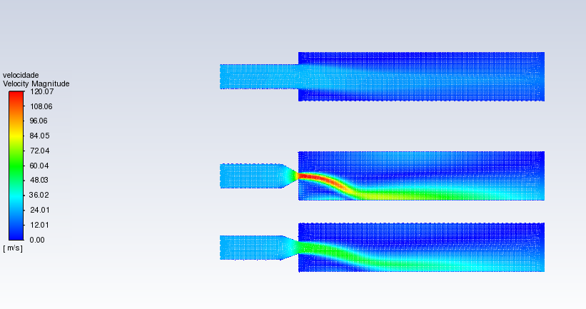
Before going to 3D simulation, i am simulating 2D using only 1 orifice. So i created 3 independent geometries with 3 different velocities (changing the orifice area).
BC: The left side is inlet-velocity (25/ms) while the right side is the pressure-outlet (-50Pa).
The model is turbulent (k-epsilon) and gravity is off. Energy off.
July 23, 2021 at 1:25 pmRob
Forum ModeratorYou may want to review mesh resolution: just because the cell quality is good it doesn't mean the mesh is. Compare the above with the result if you half the cell size. Then repeat for a further reduction in cell size.
To add, you may find some background reading on the Coanda Effect to be worthwhile.
July 23, 2021 at 2:54 pmelisio
SubscriberThanks for sharing the Coanda Effect.
Btw, the real model is a free air injection (no paralel walls up or down after the nozzle, there will be a wall after the outlet region. Thats why i want to measure the distance).
The first mesh had 29k cels.
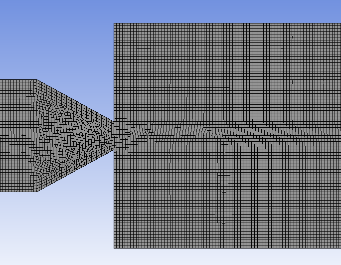
The second one, 109k:

 Result: air injection similar to first simulation, but the 1st geometry has a greater flow for me now (physic - jet formation)

However, for the 2nd and 3rd geometries, the flow is still going down as if we had different pressures, but we dont have it (symmetric).
Could the mesh at the triangular zone be bad?
July 23, 2021 at 3:27 pmRob
Forum ModeratorWhat boundaries have you got top & bottom? If they're not walls you may want to extend the domain.
July 23, 2021 at 3:53 pmelisio
SubscriberRob, this is the BCs:
 Red lines are wall.
Left side: inlet (velocity-inlet)
Right side: outlet (pressure-outlet)
REAL CASE: After the injection orifice, the top and bottom walls are really distant from the injection point;
SIMULATION: V.C. of 1 injection point, exclusively to measure the Distance vs Inlet Velocity (mass flow is constant - define the best orifice area);
However, if i haven't extended the wall, shouldn't the air flow be symmetric, as the dimensions are?
Thanks so far, Rob.
July 23, 2021 at 4:05 pmRob
Forum ModeratorWith walls look at the coanda effect, and also read up on the pitchfork bifurcation theory. You are sort of correct in that the flow should remain in the middle, but in most cases it doesn't. It will nearly always go the same way for a given mesh or experiment too, but we can't predict which way. The fact that we can influence the direction the jet takes with minimal force also provides us with some very powerful flow control abilities: it's the basis of a class of fluidic switches.
July 23, 2021 at 5:08 pmelisio
SubscriberRob, i will extend the top and bottom wall to evaluate the results ( minimizing the Coanda Effect ).
In case of big processing, i will set symmetry at middle line or rescale the area/velocity to have the same flow profile as non-scaled.
After that i'll post the result!
Regards.
July 26, 2021 at 1:48 pmRob
Forum ModeratorIf the domain height is increased then it's more likely that the jet will remain more-or-less central. It's when it's close to the bounds that it'll move and potentially stick. The results you have are more interesting, but it depends on what the objective of the study is.
Viewing 7 reply threads- The topic ‘Air Injection Distance Simulation’ is closed to new replies.
Innovation SpaceTrending discussionsTop Contributors-
4803
-
1582
-
1386
-
1242
-
1021
Top Rated Tags© 2026 Copyright ANSYS, Inc. All rights reserved.
Ansys does not support the usage of unauthorized Ansys software. Please visit www.ansys.com to obtain an official distribution.
-
The Ansys Learning Forum is a public forum. You are prohibited from providing (i) information that is confidential to You, your employer, or any third party, (ii) Personal Data or individually identifiable health information, (iii) any information that is U.S. Government Classified, Controlled Unclassified Information, International Traffic in Arms Regulators (ITAR) or Export Administration Regulators (EAR) controlled or otherwise have been determined by the United States Government or by a foreign government to require protection against unauthorized disclosure for reasons of national security, or (iv) topics or information restricted by the People's Republic of China data protection and privacy laws.


