-
-
December 2, 2024 at 2:06 pm
318661
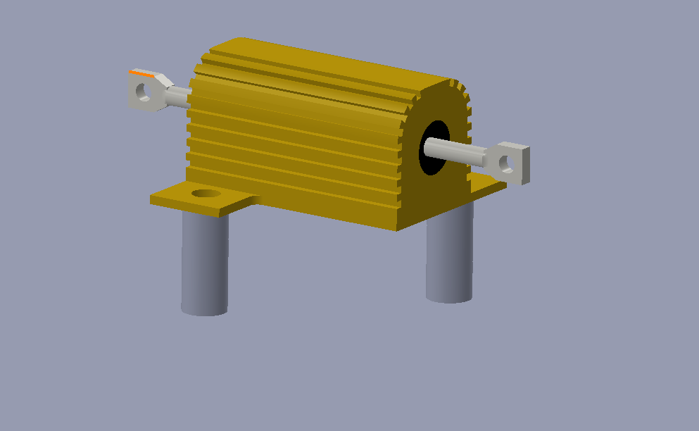
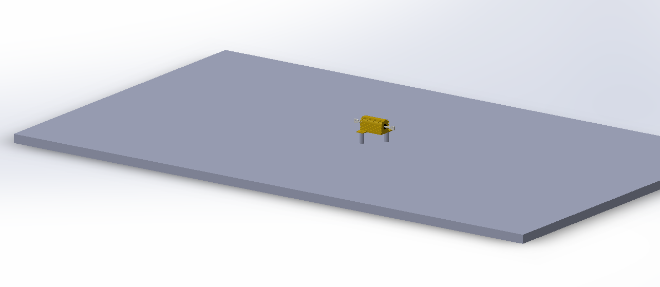
SubscriberI would need some help in order to understand better this situation.I'm a master's degree student, and I have to perform a thermal simulation of a simple electrical component, a resistor. I already made some measurements in reality: I put the resistor on a wood plate, supported by some little "rubber feet", then I fed it with certain current and voltage, in order to get a certain power (4.81 W) and I placed several thermocouples in order to get real temperatures of the chassis of the resistor (which is made by aluminum). (I took temperature on the uppersurface and on one of the flanks of the resistor).Then my aim is to perform a simulation (steady state) on Ansys Mechanical that should be able to reproduce the real behaviour of the system, that is to say it has to match the temperature measured during the experiment with the temperature which comes from the simulation. In order to do this, I built up a 3D CAD model, as you can see in the pictures above, and then I used as thermal loads:- Internal heat generation: I used a value such that, when it is multiplied by the volume of the body of the resistor (I considered it as a unique body all made by aluminum), gives a certain power (4.81W)
- Convection: I used this boundary condition on all the surfaces in contact with air, so all the external surfaces of the resistor, the rubber feets and the wood plate
Here we get to the point: when I have to model air, simplifying it as a convection boundary condition, I need to insert the "film coefficient", which is the htc of the air, and the ambient temperature, which is the temperature of the air far from the contact surface (25°C more or less).
At first, I tried with a constant htc used for all the surfaces, and I found a value (after many tries) able to match the simulated temperature with the measured one. The problem is that obviously this result lacks of generality, because if I try to use the same value of htc for another resistor, maybe bigger or smaller or with a different shape, even if the power generated is the same (4.81 W), I'm not able to match results and experiments.
Then, I guess that actually htc of air depends on many parameters, such as velocity of the fluid, geometry, temperature difference ecc.
But then the question is, how can I estimate or measure in reality a proper htc for each case?I saw that there is the possibility to specify a temperature dependent film coefficient in the Convection boundary condition, but still I don't know hot to find a proper correlation. Could someone please help me?
P.S: I also know that maybe a CFD analysis should be better, because it directly solves for fluid properties, and he can understand how the heat is transfered from the solid component to the air without specifying an htc or something like that. But still I want to understand if this simple problem, and maybe more complex problems similar to this one, can be solved also with a FEM method using Ansys Mechanical steady state thermal simulation or not. -
December 3, 2024 at 4:15 pm
dlooman
Ansys EmployeeIt appears you have mainly natural convection (no fan blowing air over the bodies.) So it would be interesting to see if the handbook values for natural convection produce the correct temperature. The fly-out menu for the film coefficient in Mechanical has an option to "Import Temperature Dependent..." One of the temperature dependent options is for stagnant air and a horizontal cylinder. This option uses the formula below. It could be close to your case.
Stagnant Air, Horizontal Cylinder, Turbulent Case. Using h = 1.24(Tw-Tb)**1/3, GrPr greater than 10e9. Ref. Holman, "Heat Transfer," McGraw Hill, 5th ed., p285.
-
December 4, 2024 at 8:20 am
318661
SubscriberGood morning, thank you so much for the help! 🙏
Yes, in my case there is only natural convection; I tried to use the temperature dependent values for the film coefficient (Stagnant Air - Horizontal Cylinder fot the resistor itself, Vertical Planes for vertical surfaces of the wood plate, Simplified for the horizontal surface of the wood plate) but still I'm not able to reach my results. The measured temperature of the resistor is 130 °C, while from the simulation it reaches 250 °C more or less.
I watched a lecture from Ansys Innovation Space
(https://innovationspace.ansys.com/courses/courses/thermal-convection-in-heat-transfer/lessons/film-coefficient-lesson-2/)Here they state that the film coefficient of the air can be estimated analytically, but I guess it is not my case since I have a complex geometry, not a simplified one). Another way to find it could be doing experiments, but actually I can't do them, finally I could use a CFD analysis to extrapolate the htc and give it to ANSYS Mechanical. Do you think there are also other ways? Because I don't think that for such a simple model I need experiments or CFD.
The only idea I have in mind is to simplify the geometry of my body making it as a simple cylinder (keeping the same volume and the same surface of the original body), and try again to use the handbook values already stored in ANSYS. What do you think about it?
-
-
December 4, 2024 at 6:29 pm
dlooman
Ansys EmployeeThat's a pretty big difference between the measured temperature of 130 degC and the FEA temperature of 250 degC! Is it possible you have a conductive heat path you're not modeling?
-
December 7, 2024 at 4:19 pm
318661
SubscriberActually I forgot to select some surfaces for the convection boundary condition, but still the temperature of the FEA is much higher than the real case (180 °C) using that kind of film coefficient; but apart from this, I think that's all okay, I just have a body which produces heat, all the contacts are set correctly, and the convection has been applied.
I start thinking that there are 2 options at the end... The first is trying to perform many experiments on different simple cases like this (I already did many of them, but, then, the problem is finding a successful correlation that links htc of the air to geometry and temperature difference of the different bodies). The other option is using CFD.
Actually I still can't imagine that for such simple cases like is so difficult to match simulations with results, any opinions?
-
-
December 7, 2024 at 4:33 pm
dlooman
Ansys EmployeeWell, 180 degC is certainly better than 250 degC! That's only about a 30% error in the film coefficient. Next steps would be to read the reference I provided to see if it applies to your case and possibly do a CFD analysis.
-
December 7, 2024 at 4:42 pm
318661
SubscriberI will do it! Thank you so much, I'll let you know if I can find something that will change the game 😁
-
December 7, 2024 at 6:24 pm
318661
SubscriberI found the chapter about natural convection on that book, and seems that estimation of htc thorugh the formulas of natural convection for an horizontal cylinder works, but only if I model the resistors as simple cylinders... If I use the original and detailed CAD model, the htc estimated in this way is much different from the htc that I must use in order to match the FEA and real temperatures. I think this happens because of the complex geometry, since we have many fins on the real resistor
Now I have 2 other questions: the first is, is it a good idea to define an htc for each surface of the geometry of the real resistor? since there are horizontal, vertical and inclined surfaces, maybe I can find a value for each of them through the formulas... It is a bit boring, but maybe could work, what do you think?
The other question is: I started doing those simple examples (just resistors that heat up and are cooled by natural convection) in order to understand better how to model the air behaviour with the convection boundary condition, inside ANSYS Mechanical. If I have to work on a more sophisticated model, for example a PCB with many components mounted on it, closed by a plastic case, should I have to evaluate again the htc of the air for each component and for each surface (both internal surfaces and external surfaces?)
-
-
-
December 9, 2024 at 4:40 pm
dlooman
Ansys EmployeeIf you are interested in studying the accuracy of handbook formulas for the film coefficient it seems like you should be as accurate as possible with the assignment of the film coefficients. I don't see customers doing this in practice though. As you can imagine it would be impractical on real models. I think most models have forced convection which is more predictable or conduction cooling of components.
-
- You must be logged in to reply to this topic.


- JACOBI Convergence Issue in ANSYS AQWA
- Is it able to solve turbomachinery using density-based solver in Fluent?
- Two-way FSI simulation
- Ensight Force_per_unit area_EV
- RIBBON WINDOW DISAPPEARED
- Fluent Meshing Error when .dsco not .stp
- Ansys Fluent for modelling Ocean Wave reactions to Wave Barriers
- Battery Pack cooling
- ISAT ABORT error
- UNASSIGNED INTERFACE ZONE DETECTED FOR INTERFACE…

-
4592
-
1494
-
1386
-
1209
-
1021

© 2025 Copyright ANSYS, Inc. All rights reserved.


