TAGGED: #fluent-#cfd-#ansys, fluent, mesh
-
-
May 16, 2023 at 3:37 pm
Jeroen Pouwels
SubscriberHey all,
First of all, I want to mention that I am a complete rookie when it comes to Ansys. I did some FEM analyses for my studies, but I am completely new to doing CFD simulations using it.
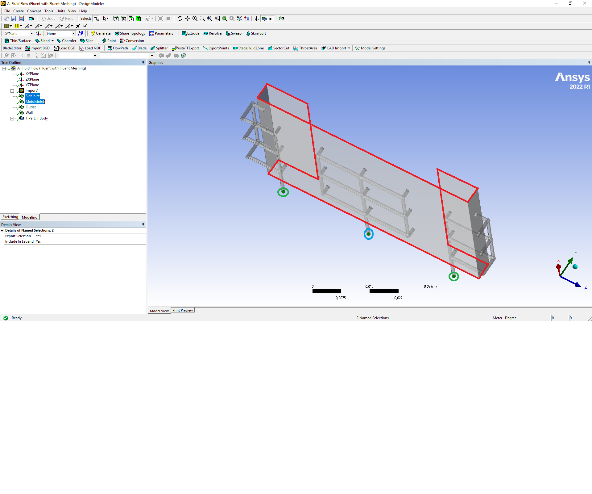
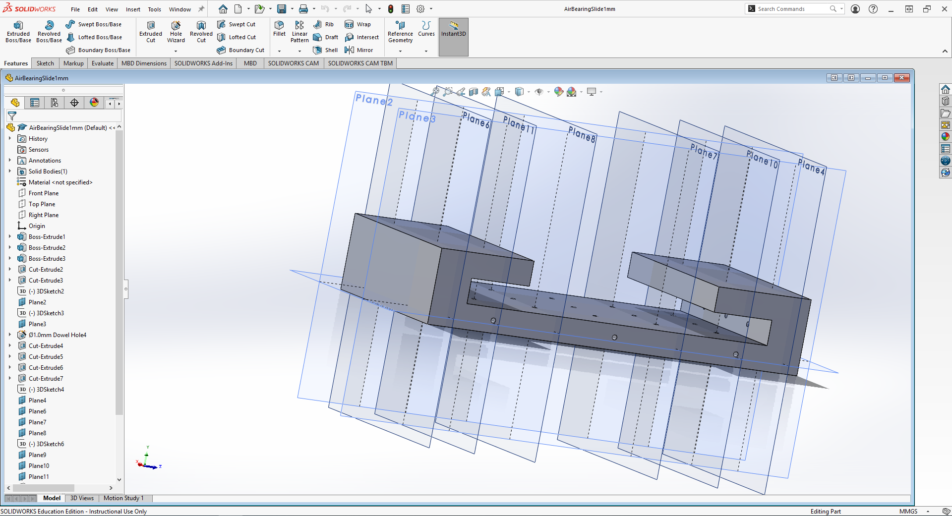
I am doing my bachelor assignment on air bearings and I am currently trying to run CFD simulations using Ansys Fluent for the air flow through a sliding air bearing. However, I do not seem to be able to get an accurate or correct volume mesh (see picture). The bearing has three inlets: two on the side and one in the middle. The one in the middle will need the highest inlet pressure since it needs to carry most of the weight of the object sliding through the bearing. The two side inlets are mainly for balance. I specified the outer edges of the rectangular parts as the outlet since this is where the flow will go into the environment again. From there, the flow's parameters are not of interest anymore. I included my solidworks assembly of the air bearing and the sliding mass going through it as well as my Design Modeler model of the volume where the air can go (see grey area in the picture as well) using a WeTransfer URL at the end of the post.
I was wondering if anyone could help me with creating a good mesh and setting the model up for a simulation. Thanks in advance!
-
May 16, 2023 at 4:16 pm
Federico
Ansys EmployeeHi,
are you using any of the Fluent Meshing workflows? Also, what are the errors highlighted in your image? Self-intersections? Overlapping faces?
-
May 18, 2023 at 9:09 am
Jeroen Pouwels
SubscriberHi Federico, I indeed use Fluent Meshing Watertight Geometry workflow. I believe it is overlap, so my main question at the moment comes down to how to mesh this very thin (10 micron) layer of air and how to mesh the air channels below it without creating overlap.
-
-
May 17, 2023 at 7:18 am
NickFL
SubscriberI am having difficulty visualizing it at that angle. Pehaps you could show the geometry a better picture with some descriptions of where the BCs are, etc. Do you need or want to use Fluent Meshing or can you use ANSYS Meshing? Typically air bearings are very thin in one direction so it is useful to decompose the geometry to obtain a high quality hex mesh with high aspect ratio elements. Simply using a “tet-bomb” approach will result in too many elements. Are you going to include mesh motion in your simulation? These are all important things to consider before undertaking such a project.
Welcome to the world of CFD:)
P.S. Most of us cannot download files from random sites. Please make images (and marked up images are even better) and post them here. ANSYS has created this nice forum that hosts these pictures quite well.
-
May 18, 2023 at 9:22 am
Jeroen Pouwels
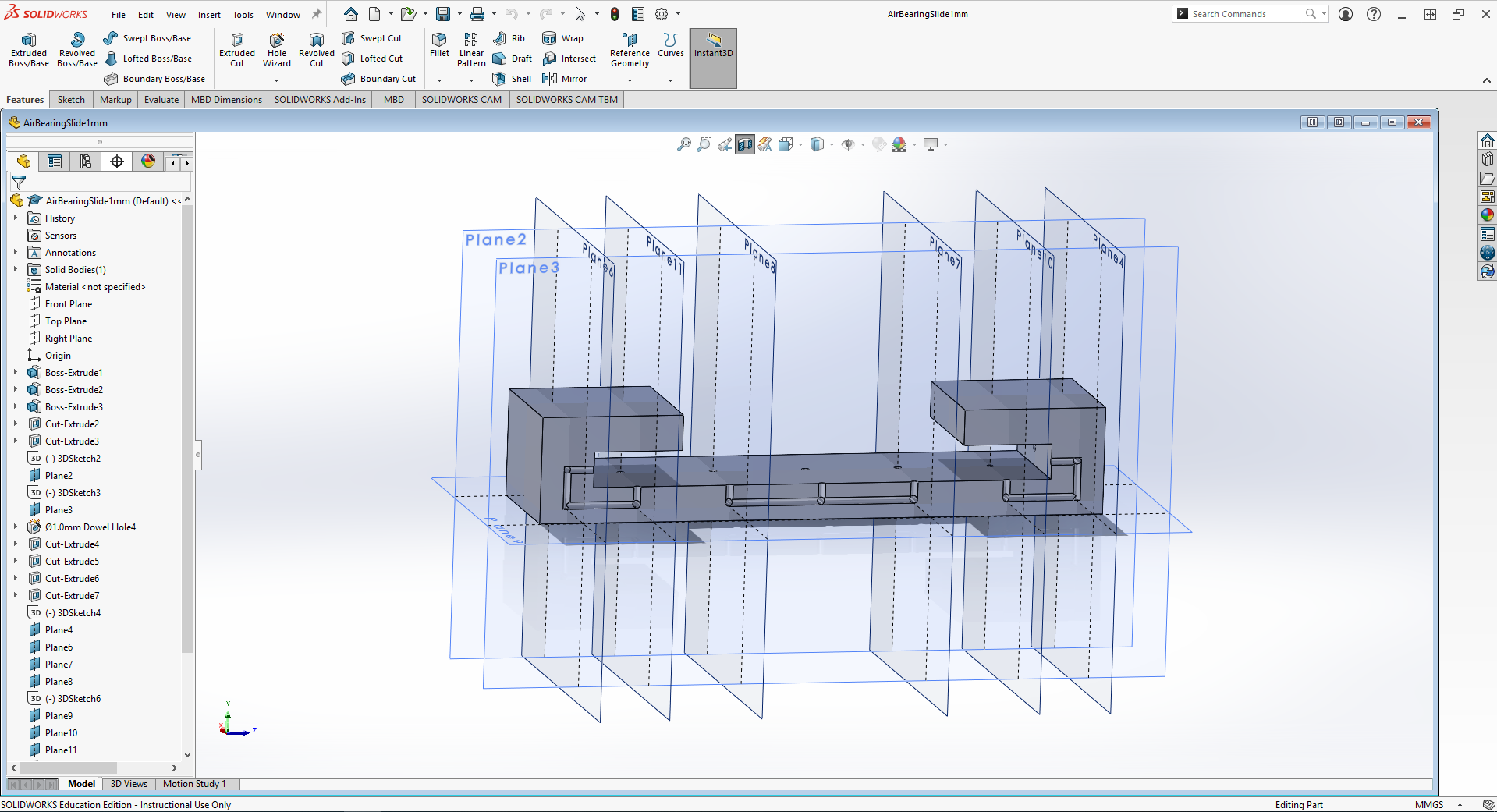
SubscriberHi Nick, thanks for the reply. I thought it would be best to use Fluent Meshing for this, but I am completely open to suggestions. I added a better image regarding the geometry of the volume as well as an image of the bearing itself. I hope this makes it easier to visualize. The outlet is marked red, the middle inlet is marked blue and the side inlets are marked green. Every other face is selected as the wall.
It seems like you know how to mesh the thin airflow between the slider and the bearing as well as the airflow channels underneath. Could you maybe explain more thoroughly how you would approach that? The airflow between the slider and bearing is 10 microns thick and the channels have a diameter of 1 to 2 mm, but I will start with 1mm.
-
May 18, 2023 at 11:11 am
NickFL
SubscriberMy recommendation would be to do this in ANSYS Meshing. Read up on body decomposition and multibody parts in ANSYS.
If I were to create it, I would create several bodies for the inlet tube network (I don't think they are all connected are they? I think I see three independent paths.) and then a mutli-body part for the thin air channel. You could create this in such a way that you would not have to go back and remesh when you are in a different position from the nominal. Instead, you would simply scale the mesh to adjust the dimensions. The downside to this approach is, you would not have a congruent mesh (1:1) at the tube/channel interface, but you could use a finer mesh to have the interface approach be effective.
-
May 18, 2023 at 11:27 am
Jeroen Pouwels
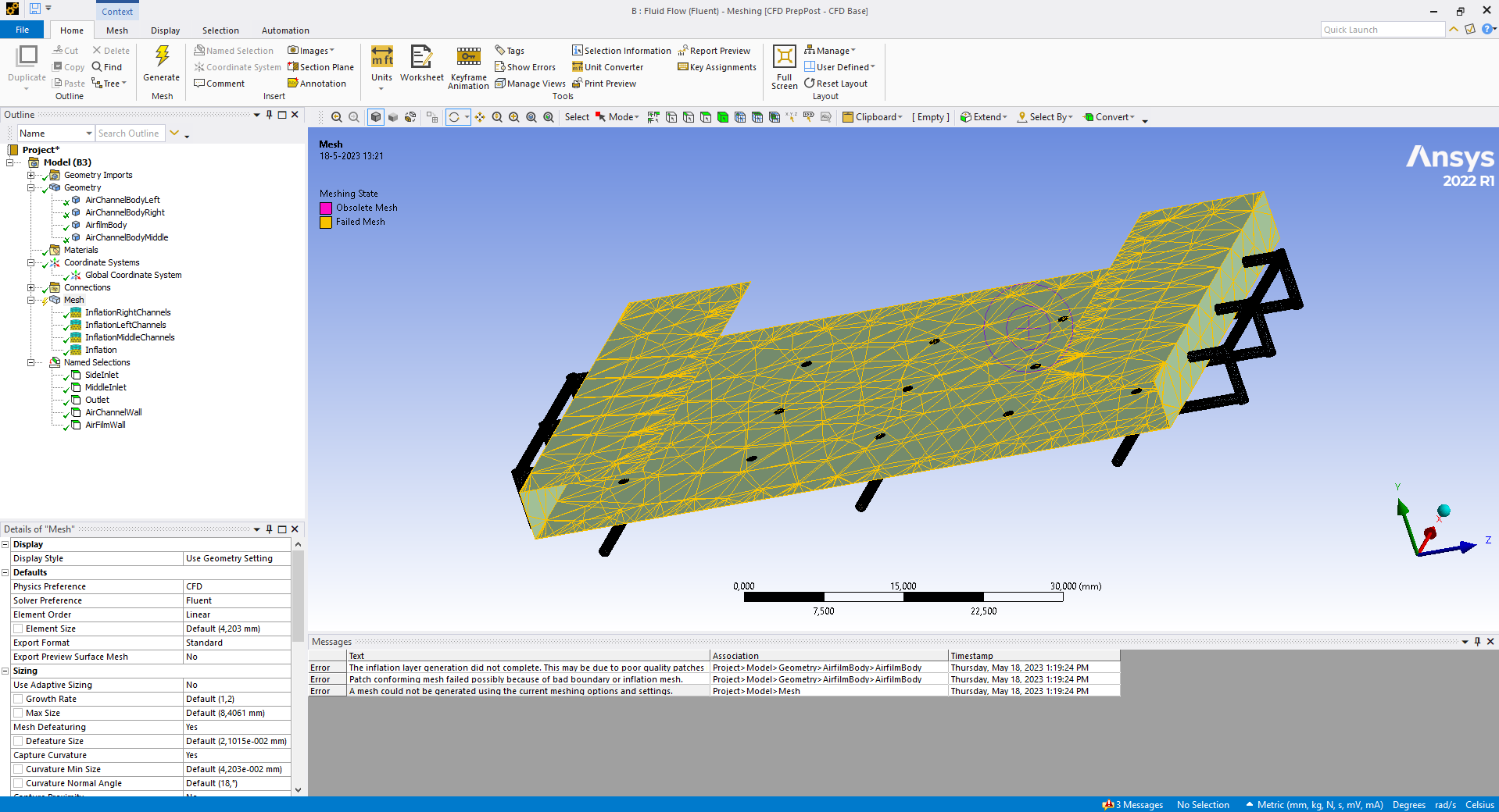
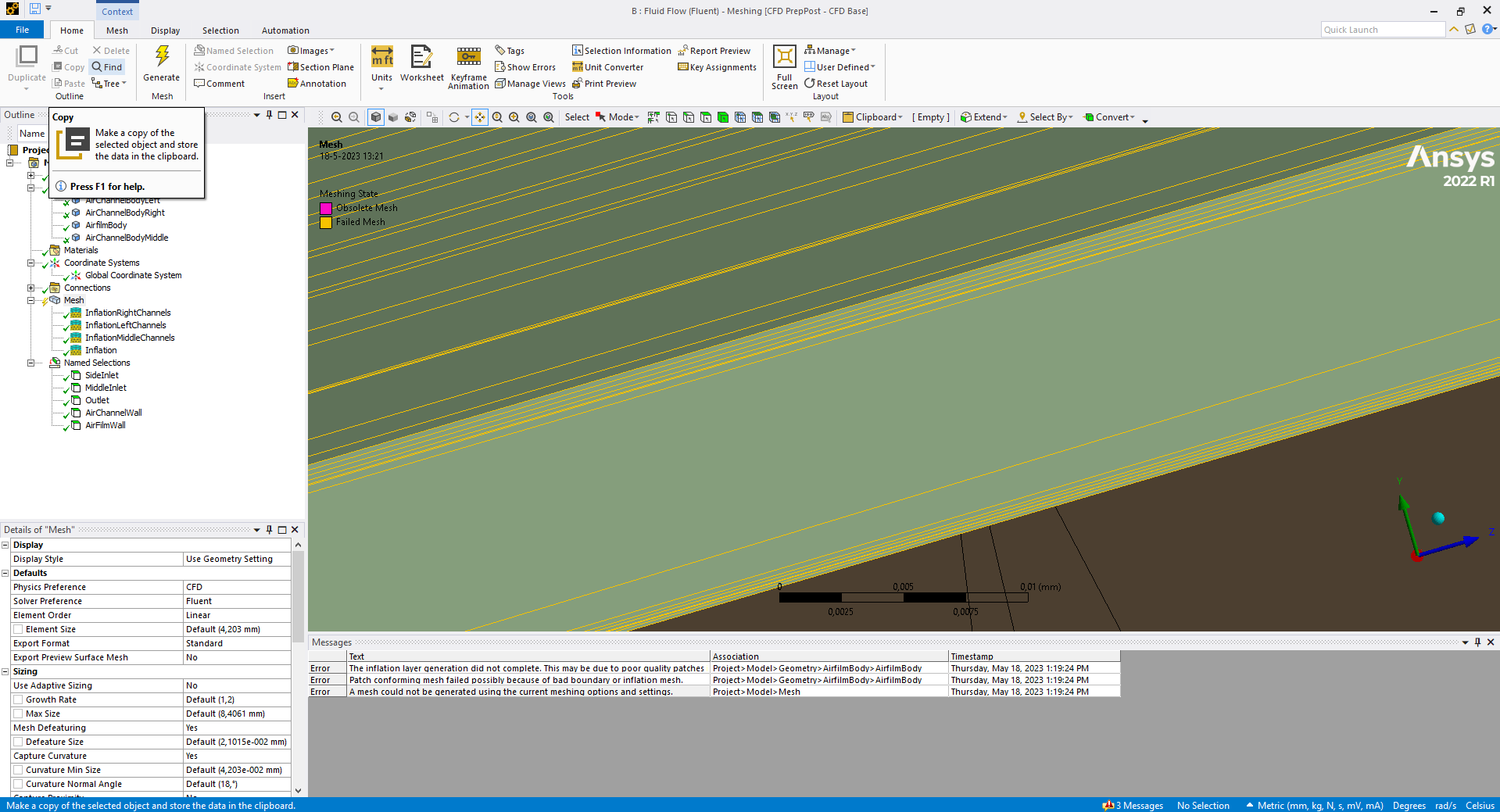
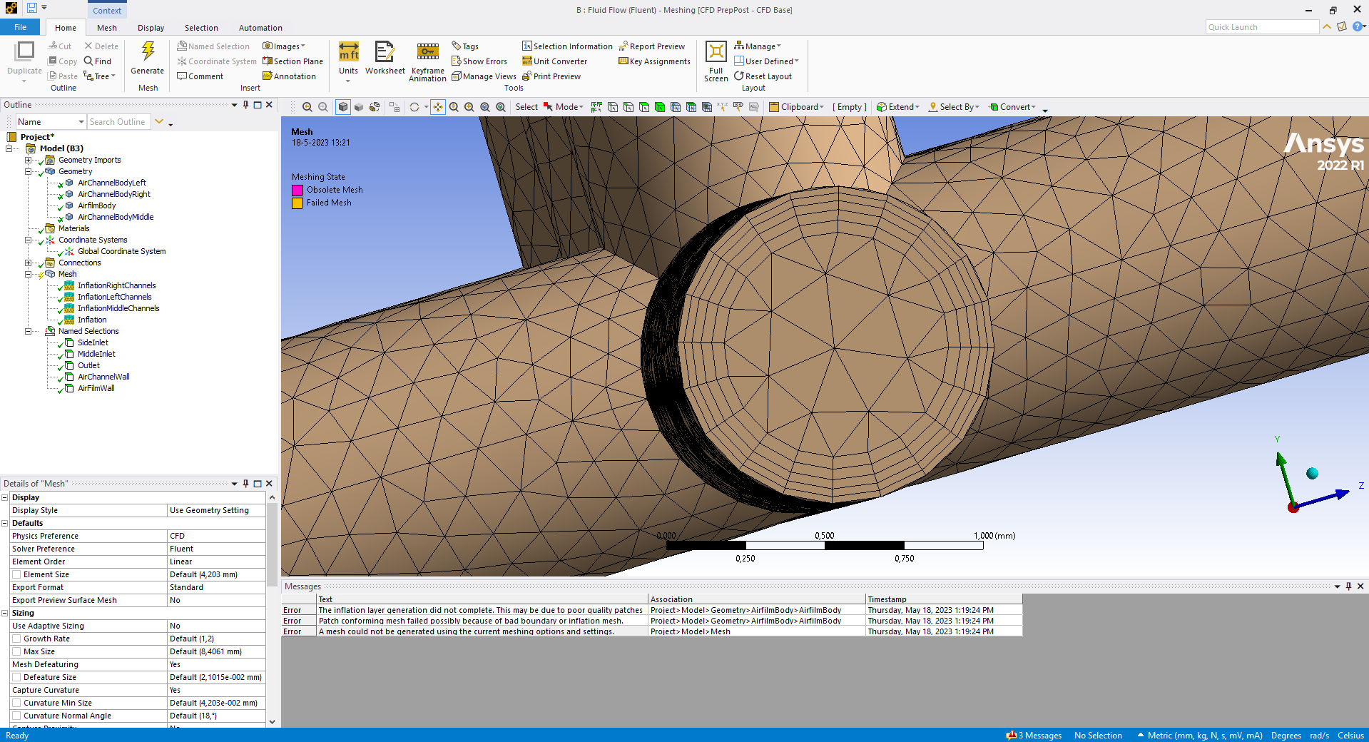
SubscriberOkay, thank you, I will switch to that then. What I did now is I created the three bodies for the tube networks and I created a fourth body for the thin layer of air. The only thing I adjusted to the standard mesh is the addition of inflation layers for the tubes. I am currently trying to add an inflation layer for the thin layer as well but that gives the following error messages:
- The inflation layer generation did not complete. This may be due to poor quality patches in the surface mesh, sharp geometric features, or narrow passages.
- Patch conforming mesh failed possibly because of bad boundary or inflation mesh.
- A mesh could not be generated using the current meshing options and settings.
I also added some pictures of how it looks now
Would you suggest any other edits to the standard mesh for the piping system? And how do you suggest that I mesh such a thin layer?
Thanks for your help already!
-
May 18, 2023 at 11:36 am
NickFL
SubscriberThe thin air channel will not mesh well with tets -- especially with tets the sizing it is trying there. The body looks simple enough to sweep/multizone, but I would cut it up further so that you could have a resolved mesh where the inlet come in.
As for the piping network, I would try and see if you could use multizone to mesh these. Then you could have more high aspect ratio hex elements to reduce your mesh count.
-
May 19, 2023 at 10:47 am
Jeroen Pouwels
SubscriberHmm where do you suggest I cut it up? Also, when trying to use multizone with hex elements for the piping I get the following error: MultiZone blocking decomposition failed.
Do you know what this means?
-
May 23, 2023 at 6:18 am
NickFL
SubscriberSee below for a simple example. I would have something like this around each of the holes. The inner circle should be bigger than the max deviation of the feeder pipes. There should also be at least 6, probably 8 or even better 10 layers through the thickness (into and out of the screen). The mesh sizing here is too coarse, but I wanted to demonstate the idea.
-
May 23, 2023 at 8:46 am
Jeroen Pouwels
SubscriberOoh, I see what you mean now, thanks. After cutting it up, what meshing methods did you use here then?
-
May 23, 2023 at 10:54 am
NickFL
SubscriberThose are all 6-sided blocks, so the sweep works well. You can put sizing on all the edges with biases and everything to really control the mesh.
-
May 23, 2023 at 11:36 am
Jeroen Pouwels
SubscriberOkay, thanks. I will try it later today!
-
-
-
May 19, 2023 at 11:09 am
Rob
Forum ModeratorSlicing and dicing geometry is a bit of an art form, and one that's not been practiced much for several years. Have a look at the various meshing courses, and read up on Sweep (Ansys Meshing). Multizone is going to struggle becuase of the pipe orientation connecting into the model from multiple directions (y & z).
-
May 23, 2023 at 11:37 am
Jeroen Pouwels
SubscriberOkay, thanks
-
-
May 23, 2023 at 10:55 am
NickFL
SubscriberIs that your way of saying that I am old?
-
May 23, 2023 at 2:08 pm
Rob
Forum ModeratorNo comment! ;) Given I learnt to fully block mesh (single block, none of this multi-block stuff) with cartesian cells I'm not sure what that would make me.... I prefer experienced!
-
-
- The topic ‘Air Bearing CFD meshing’ is closed to new replies.


-
4833
-
1587
-
1386
-
1242
-
1021

© 2026 Copyright ANSYS, Inc. All rights reserved.


