Hello, I have built a model of a bare-die FCBGA package which consists of
- Die (X = 25mm, Y = 25mm, Z = 0.78mm)
- Below the Die there is Underfill&Solder layer (X = 25mm, Y = 25mm, Z = 0.075mm)
- Below the Underfill&Solder, there is a Substrate (X = 50mm, Y = 50mm, Z = 1mm)
- Below the Substrate there are square BGA balls (X = 0.5mm, Y = 0.5mm, Z=0.5mm)
- On top of the Die, there is a TIM1 layer (X = 25mm, Y = 25mm, Z=0.05mm)
- On top of the TIM1 layer, there is a Heatsink with 7 fins. Heatsink base (X = 25mm, Y = 25mm, Z=0.6mm) and each fin (X = 25mm, Y = 0.85mm, Z=1.9mm)
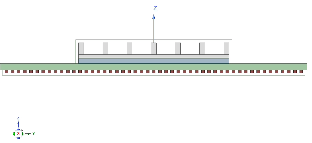
For all geometries, I have used the Draw function and defined each material properties (thermal conductivity). See below how the geometry looks like from the right:
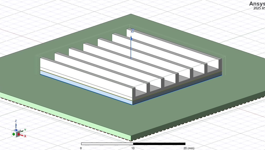
This is a dimetric view:
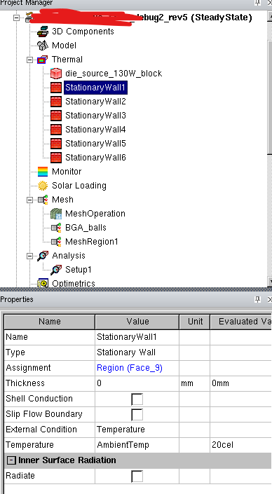
I have defined Wall thermal conditions on the outside air box with ambient temperature and a power source in the die:
I have attempted to conduct meshing. In my first attempt, I just used a global auto mesh (normal), but there was no mesh created for BGA balls, TIM1 layer and Underfill&Solder layer that are thin.
Afterwards, I tried to add mesh regions: one region for BGA balls, Die, Heatsink, Substrate, TIM1 and Underfill&Solder respectively. I extended the mesh region boundaries of BGAballs, TIM1 and Underfill&Solder so they are not aligned with the corresponding objects (e.g.I extended the mesh region of TIM1 by 0.1mm outside the TIM1 object). I define advanced meshing with the following parameters for TIM1:
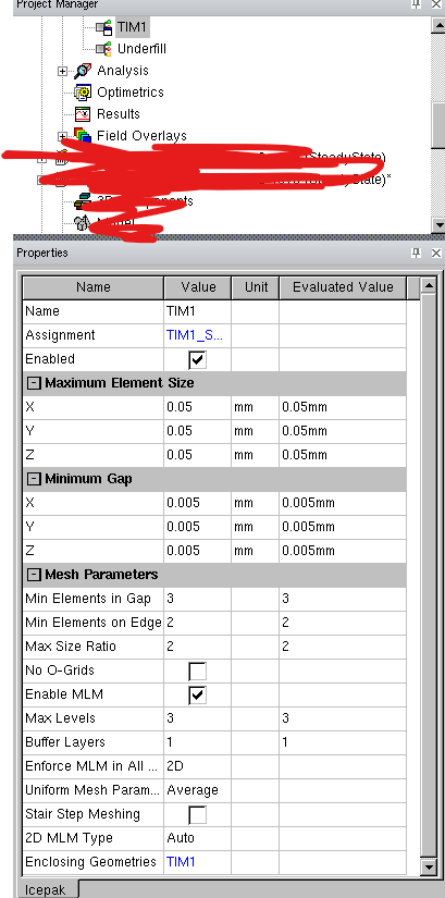
With these settings, I get a warning that die_source_130W_block is not meshed

With the described geometry, what would be the meshing approach you suggest? So which objects to place in one mesh region, and what advanced parameters should be set in the mesher to create proper mesh (maximum element, minimum gap, mesh parameters)?
Thanks


