
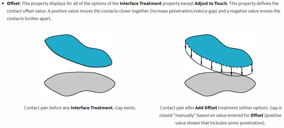
TAGGED: adjust-to-touch, contacts, frictional-contact
-
-
February 12, 2021 at 12:08 pm
Rameez_ul_Haq
SubscriberPlease observe the following frictional contact.
February 13, 2021 at 12:57 ampeteroznewman
SubscriberArray
Adjust to touch measures the distance from each contact node to the target surface. The minimum distance has a dx, dy, and dz component. Adjust to touch moves every node by dx, dy, dz so that at least one node is closed. In your case, you have a cylinder against a flat, so 40 nodes ended up with a zero distance. All the nodes with a distance larger than the minimum remain open.
February 13, 2021 at 11:31 amSubscriberArray, I don't understand when you said, ''moves every node''. I mean I have already created the mesh, how can the nodes move? I have a specific solid onto which I have meshed solid elements. Now assume I have a distance of dx=dy=dz=10 mm minimum, then moving every node by that distance might create some huge moments which can affect my results adversely. Isn't it?
February 13, 2021 at 12:53 pmSubscriberArray
Adjust to touch should only be used when the gap is insignificantly small, such that moving the nodes will have no significant effect in the model, other than allowing the solution to start. When there is a large gap, you must move the body to close the gap, otherwise, what you said will happen. Don't turn on Adjust to touch without first evaluating the initial gap status and looking at the size of the gap before selectively turning on Adjust to touch on those few contacts that need it because they have a tiny gap.
January 5, 2022 at 8:31 amSubscriber.peteroznewman, I tried using Adjust to Touch option for the model below. The surface body is given offset type of bottom, as shown the figure below. Gap between the surface body (marked in green) and bottom face of the solid body is 2.1 mm. I have given a thickness of 2 mm to the surface body.
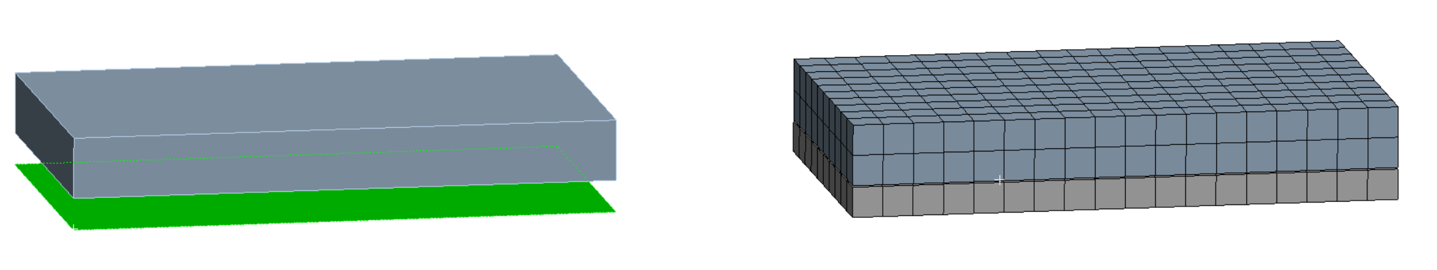 So the distance between the top most face of the surface body and the bottom face of the solid body is 0.1 mm. What if I use option adjust to touch? Will this top most face of the surface body will move by 0.1 mm only, or it will move the complete surface body by 0.1 mm, or it will make the surface body itself move 2.1 mm (so that it just overlaps with the bottom face of the solid body)?
.January 5, 2022 at 1:05 pmSubscriber.Rameez_ul_Haq
The gap measured by the contact elements measures 0.1 mm so when you use Adjust to Touch, the contact elements are offset by 0.1 mm from the structural nodes to close the gap.
To clarify the "moves every node" statement, that refers to the contact element nodes, which are initially created coincident with the structural nodes on the body face. The Offset section of the contact definition allows you to move the contact element nodes into the body or outward from the body. Adjust to Touch just automates the setting the value after measuring the minimum gap.
.January 5, 2022 at 1:38 pmSubscriber.peteroznewman,
The gap measured by the contact elements measures 0.1 mm
I mean which gap are you talking about? Gap or the geometric gap? The geometric gap infers, I guess, the gap between the surface body and the bottom face of the solid body, which is 2.1 mm. Now, the gap you are saying is 0.1 mm, which makes me believe that the gap is actually the distance between the offsetted face of the surface body (which is 2 mm away from the actual surface body) and the bottom face of solid body. Is that correct?
I think you are assuming that I am choosing the top face for the surface body as target, while the bottom face of solid body is contact. What if I keep the bottom face of the solid body as contact, but change the target face to be the bottom face of the surface body. I know this doesn't make any sense, but why not do it for the sake of understanding. Now, the pinball radius is kept at 2.5 mm implying that the frictional contact will get detected. But what would the gap be now? And what would adjust to touch do now, here?
.January 5, 2022 at 1:49 pmSubscriber.Rameez_ul_Haq
To answer your first paragraph of questions, you have the model, so tell me what you find.
To answer your second paragraph... you have a surface body with structural shell elements with an offset of bottom, so the nodes are on the bottom and the top of the shell element is 2 mm above the nodes. When you add contact and specify Top, a new layer of contact nodes are placed 2 mm above the structural nodes. Those contact nodes are 0.1 mm away from the Target elements on the face of the block. When you adjust to touch, the contact nodes are placed 2.1 mm above the structural nodes.
.January 5, 2022 at 5:51 pmSubscriber.peteroznewman, well I deleted the model because it was only an example. But just built it again, and here are the results.
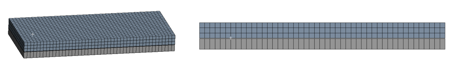
Surface Body below, solid body above. Gap between the surface body and solid body = 2.1 mm. Thickness given to the surface body (using offset type = Bottom) = 2 mm. The gap between the upper most face of the surface body and the bottom face of the solid body = 0.1 mm.
CASE 1: (CONTACT = Given to Surface Body, TARGET = Given to Solid Body, Pinball radius = 2.5 mm, Interface Treatment = Add Offset, No Ramping, Target Shell Face = Top).
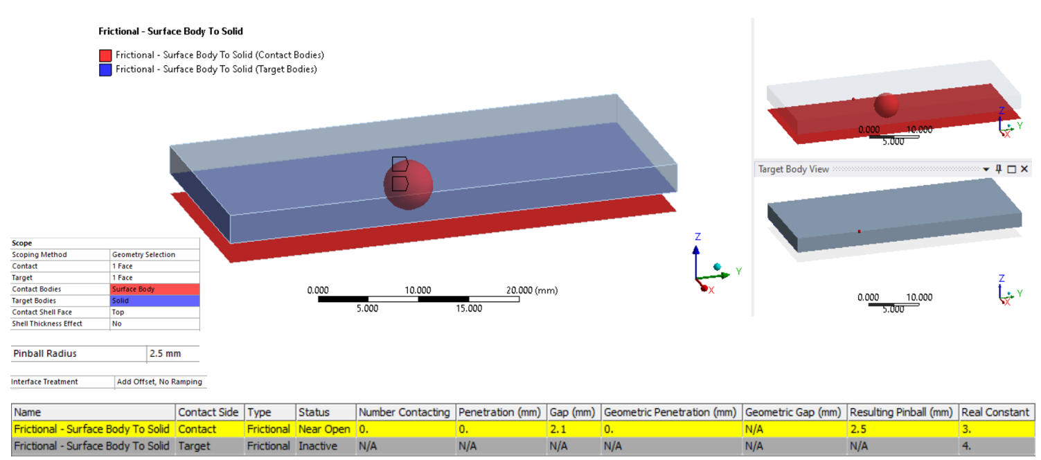 The gap is still 2.1 mm, and not 0.1 mm (which you were signifying). Why is that so? A gap of 2.1 mm implies that the force transfer will not take place at the top most face of the surface body (which is offsetted by 2 mm), but infact will take place at the face (of surface body) where the original surface body is present (I mean at original location of the nodes of this surface body). Right? But this is something I don't want. I want the force transfer to take place at the 2 mm offsetted face of the surface body. Plus, I don't see any value for geometric gap, why?
CASE 2: (CONTACT = Given to Solid Body, TARGET = Given to Surface Body, Pinball radius = 2.5 mm, Interface Treatment = Add Offset, No Ramping, Target Shell Face = Top).
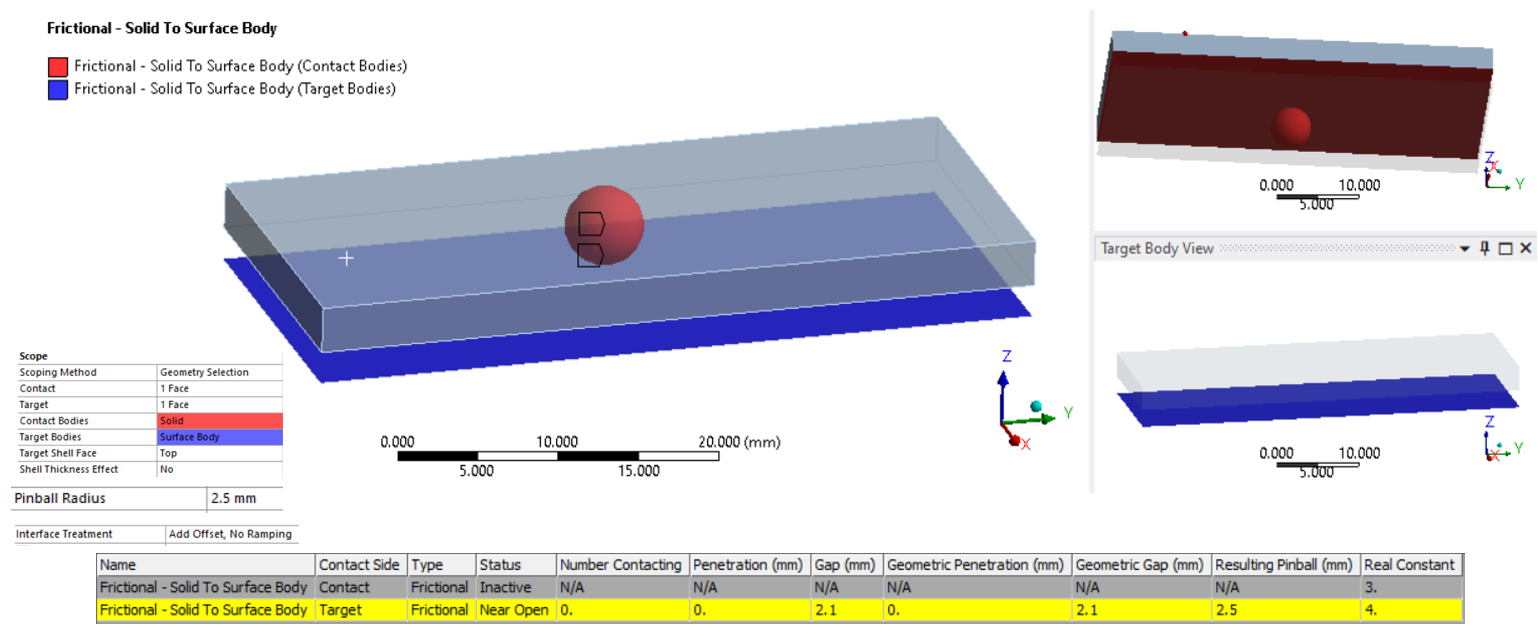 Again, the same thing. The contact is tracked but the gap is still 2.1 mm (and not 0.1 mm as you were saying). This confuses me why. What can I do to make the force transfer to happen at the top most face of the surface body which is offsetted by 2 mm. However, now I geometric gap as well. I don't know why do I see it now but couldn't see it in 1st case.
Note that when the interface Treatment was set to 'Adjust to Touch', both the cases gave GAP = 0 mm ( (because the closest contact elements translates to close the gap). But how much amount they move? 0.1 mm, or 2.1 mm? I don't know.
.January 5, 2022 at 9:30 pmSubscriber.Rameez_ul_Haq
The case you are studying, with a surface body on the opposite side from the contact, I never use. I either put the surface body in contact with the solid body, so I don't need an offset, or I have a surface body at the midsurface, then I turn on Shell Thickness Effect, and it automatically calculates the offset.
You can use Offset (No Ramping) of 2 mm. I expect that will provide a 0.1 mm gap.
 SHELL THICKNESS EFFECT
This property appears when the scoping of the contact or target includes a Surface Body. Options include:
- Yes: Include the property.
- No (default): Exclude the property.
When set to Yes, the contact object becomes under-defined if the Offset Type of any scoped surface body is set to a value other than Middle. In this situation, the following error message will be displayed: "The shell thickness effect of a contact pair is turned on; however, the offset type of a shell body in contact is set to other than Middle. Set its offset type to Middle."
.January 6, 2022 at 9:57 amSubscriber.peteroznewman, so I just want to confirm this, sir. If I use offset of 2 mm, and assume the gap now decreases from 2.1 mm to 0.1 mm, then does it mean that the force transfer will now happen at the top most face (which is offsetted by 2 mm) of the surface body, with the bottom face of the solid body?
.January 6, 2022 at 1:26 pmSubscriber.Rameez_ul_Haq
Yes.
.January 6, 2022 at 6:58 pmSubscriber.peteroznewman, so does it make a difference (in terms of displacements, stresses, strains etc within the surface body) if the force transfer happens on the top most face of the surface body (which is offsetted by 2 mm) or if the force transfer occurs on the actual nodes of the surface body (which is 2.1 mm away from the bottom face of the solid body)?
.January 7, 2022 at 12:51 pmSubscriber.Rameez_ul_Haq
Shell elements are intended for thin-walled structures. That means the shell thickness is a small number compared with the overall size of the part.
Shell elements accurately capture lateral deformation caused by pressure, and bending moments, as well as in-plane deformation caused by in-plane loads.
When the shell element neutral axis is offset from the shell element nodes, the element formulation includes that effect on the stiffness at the nodes.
I don't know, but I expect that the contact algorithm includes the small moment that a contact force could create about the neutral axis. You do some experiments to build your understanding of this effect.
In the figure below, a surface has been meshed with blue shell elements. The shell nodes are yellow. The shells have a thickness represented by the light blue boxes. Contact has been defined on the top of the surface. The contact nodes are green. Three types of Offset are shown below. The contact is always the same distance from the neutral axis.
.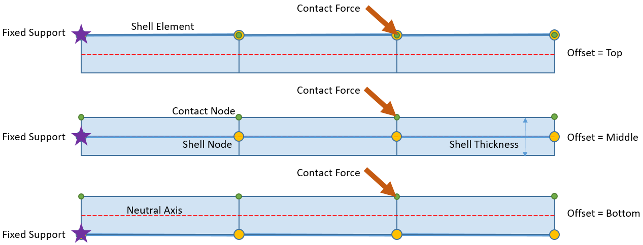 The one effect that might be detectable in the figure above is that the horizontal component of the contact force has a different moment about the Fixed Support depending on the Offset. In a real problem, the thickness of the part would be small and the part would be large and the fixed support would be distant, so there would probably be no detectable effect.Viewing 13 reply threads
- The topic ‘‘Adjust to Touch’ option in frictional/frictionless contact.’ is closed to new replies.
Innovation Space Trending discussions
 Top Contributors
-
peteroznewman
 4833
4833 -
scabo
 1587
1587 -
Dennis Chen
 1386
1386 -
javat33489
 1242
1242 -
Shyam Prasad V Atri
1021
Top Rated Tags
© 2026 Copyright ANSYS, Inc. All rights reserved.
Ansys does not support the usage of unauthorized Ansys software. Please visit www.ansys.com to obtain an official distribution.
-


