
-
-
December 26, 2021 at 5:38 pm
drrkozdemir
SubscriberHello,
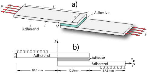
I need to do a fatiuge analysis on adhesively bonded single lap joint. I attach the image below, I’m a student and new to the ansys.
December 26, 2021 at 5:52 pmRameez_ul_Haq
Subscriber,so what is the problem, or what is the question?
December 26, 2021 at 5:56 pmSubscriberI dont know how to add adhesive in two solid parts, how can I use it, do I need to skecth it like another part or do I use contacts?
adherends are aluminum thx for the quick response
December 26, 2021 at 5:58 pmSubscriberI dont know how to add adhesive in two solid parts, how can I use it, do I need to skecth it like another part or do I use contacts?
adherends are aluminum thx for the quick response
December 26, 2021 at 6:57 pmSubscriberthere are two options you can use. Apply a bonded contact between the top face of the adhesive and lower face of the part above it, and add another bonded contact between the bottom face of the adhesive and the upper face of the part below it.
Second option is to use a use shared topology in the SpaceClaim, and create a shared topology between these regions. This way, you don't have to use bonded contact anymore.
December 26, 2021 at 7:16 pmSubscriberthx for the reply
Do I need to add a new material for the adhesive section and select the relevant properties via ansys?
I mean from here:
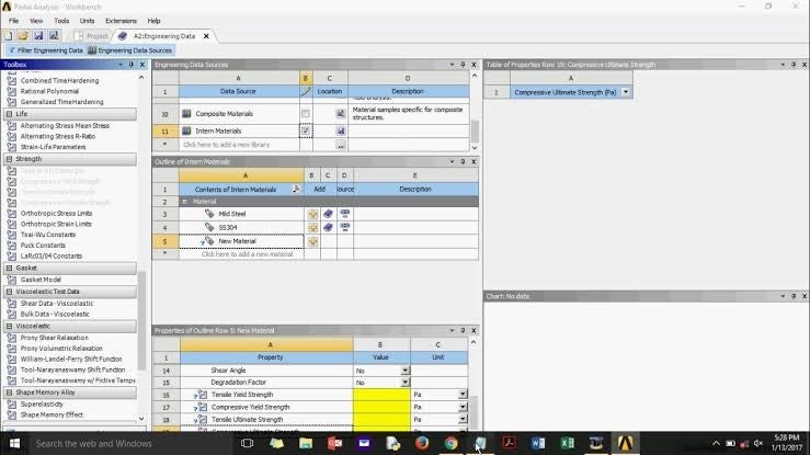
December 26, 2021 at 7:46 pmSubscriber,if you want to observe the behavior of the adhesive (like will it fail or not under the applied loads and boundary conditions), then you have to add the material for the adhesive. Either you can choose the material from the ANSYS library, or you can also add user defined material in the Engineering Data. If you are using ANSYS2021R1 and above, then there is no need to add the material properties from the Engineering Data, if you want to add an already existing material from ANSYS library. Open Model, you will see an option for 'Materials' in the tree. Then search for a material, and then click '+' option on right of that material. Your material is automatically added. You can then define your structural parts to have this material.
If the answers helped, pelase accept the answers.
December 26, 2021 at 8:59 pmSubscriberThank you so much for your guidince and patience.
I will follow the steps below.
1) Selecting the relevant material from the material library for aluminum. Specify and add material properties for the adhesive.
2) Drawing two aluminum plates and adhesive and establishing a contact relationship as you described. The adhesive will be drawn just like aluminum and the material with the properties of the adhesive material I created will be selected.
3) Put into fatigue analysis.
December 26, 2021 at 9:07 pmSubscriber,absolutely correct.
December 27, 2021 at 2:24 pmpeteroznewman
SubscriberTo use the Fatigue Tool, the material in Engineering Data needs Stress-Life data.
To obtain Stress-Life data, fabricate many samples and test sets of them at multiple levels of stress until they fail.
January 13, 2022 at 2:08 amSubscriberDear Peter IÔÇÖm at the end of my project, and now I see that why I need stress-life data. For aluminum Ansys have the data for S-N but unfortunately for the adhesive I cant find any data. IÔÇÖm not doing an experement for this and I couldt find any adhesive S-N data on net.
Can you help me for this situation, kind regards.
January 13, 2022 at 12:57 pmSubscriberYou never said what the adhesive was...I don't see how I could help.
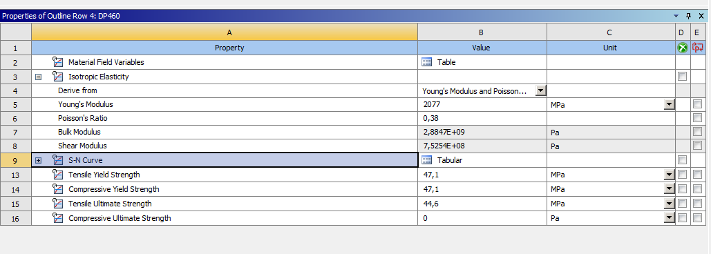
January 17, 2022 at 12:07 amSubscriberDearand I created the component, for the stress-life data my tutor said I could get my own values. So I added an adhesive called DP460. Below you can see the data
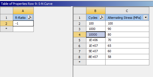
Full proporties of the DP460
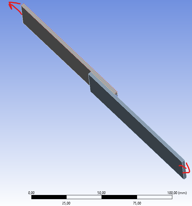
My model is a adhesively bonded SLJ and I tried to apply force both sides of the SLJ
But when I use the fatiuge tool, I get error says :
''An internal solution magnitude limit was exceeded. (Node Number 30548, Body Parca2|Y_kseklik-Ekstr_zyon1, DOF UZ) Please check your Environment for inappropriate load values or insufficient supports.You may select the offending object and/or geometry via RMB on this warning in the Messages window.Please see the Troubleshooting section of the Help System for more information.''
and
''An internal solution magnitude limit was exceeded. Please check your Environment for inappropriate load values or insufficient supports.Please see the Troubleshooting section of the Help System for more information.''
Not using real S-N values for the glue may have caused the error, unfortunately I couldn't get help from my instructor in this regard and I've been trying everything. I'm using the aluminum from the library for the sticky plates. (adherend) For the component I use Solidworks then I transferred it to Ansys.
Whenever I search the web about these errors, it turns out that there may be a problem with the contacts. Once again, I'm asking for your help. I attached my work. Thank you again.
January 17, 2022 at 12:12 amSubscriberPlease open Project11.wbpj in Workbench, then use File Archive to save a .wbpz file, which includes the Project11_files folder. The .wbpj file on its own is useless without the _files folder of the same name.
January 17, 2022 at 12:39 amSubscriberJanuary 17, 2022 at 12:48 amSubscriberOne of the force is reversed you propably noticed thats a mistake, it needs to be like on the image I upload before
January 17, 2022 at 1:35 amSubscriberDelete one of the forces and replace it with a Fixed Support on that face.
One improvement to the model would be to open the Geometry in SpaceClaim and click the Share button on the Workbench tab. Then when you open the model in Mechanical, delete both contacts because the three bodies will be connected with shared nodes.
January 17, 2022 at 2:12 amSubscriberfirstly thank you for all your support, this project is really critical for me and you always help.
I tried once with one fixed support and one force, I will ask my tutor if he accepts then work is done
I struggled with this problem because he told me to load from both sides, when I searced the error ''An internal solution magnitude limit was exceeded...'' I found a video that says use command and type ''1e30'' and it worked, I have no idea what is it but I wanted to share it with you because you helped me a lot. Maybe it will help you in your future work.
The link is https://www.youtube.com/watch?v=9vCyjw08OUQ
I will share the final version of project to you, maybe you want see with a command. Do the results appear to be correct in an analysis for fatigue?
Thank you again Mr. Peter. We are lucky to have you on this forum. Whenever I do research, your name is there.
January 17, 2022 at 5:29 pmSubscriberI watched the video. It's a diagnostic procedure to find a mistake in a model. Step 1 turns off Solver Pivot Checking, and inserts a command to allow displacements as large as 1e30. A missing bonded contact is identified and added to the model, then the changes in step 1 are undone so the solver settings are returned to normal before solving again to get a valid solution.
The diagnostic procedure I use to find a mistake in a multibody static structural model is to do a Modal analysis solution. If that was done to the model in the video, the same part would have been floating around in space in modes 1-6.
Your model has no connection to ground. 3D Static Structural models need to be connected to ground in all six degrees of freedom, three translations and three rotations. Transient Structural models don't require that because the missing ground connection can be replaced by inertia forces. There is a trick to apply accelerations to a Static Structural model and not require a connection to ground, but there is no need for that in your model.
The solver checks for zero pivot errors because during solving, numerical errors can be greatly magnified when a pivot value in the matrix approaches zero. You can read about that in a Numerical Methods book.
There are some refinements to your model that would make it behave more like the samples in the lap shear test. For example, there is a constraint that prevents the end with the applied force from rotating and lifting. That can be added to the model with a remote displacement constraining those two degrees of freedom while leaving the axial translation free.
Viewing 18 reply threads- The topic ‘adhesively bonded single lap joint’ is closed to new replies.
Innovation Space Trending discussions
 Top Contributors
-
peteroznewman
 5799
5799 -
scabo
 1906
1906 -
Dennis Chen
 1420
1420 -
javat33489
 1305
1305 -
Shyam Prasad V Atri
1021
Top Rated Tags
© 2026 Copyright ANSYS, Inc. All rights reserved.
Ansys does not support the usage of unauthorized Ansys software. Please visit www.ansys.com to obtain an official distribution.
-


The Ansys Learning Forum is a public forum. You are prohibited from providing (i) information that is confidential to You, your employer, or any third party, (ii) Personal Data or individually identifiable health information, (iii) any information that is U.S. Government Classified, Controlled Unclassified Information, International Traffic in Arms Regulators (ITAR) or Export Administration Regulators (EAR) controlled or otherwise have been determined by the United States Government or by a foreign government to require protection against unauthorized disclosure for reasons of national security, or (iv) topics or information restricted by the People's Republic of China data protection and privacy laws.
