TAGGED: #motor-cad, Stress-Analysis
-
-
September 16, 2024 at 8:52 am
nkb221
SubscriberWhat is an adequate adhesion factor for IPM rotors for stress analysis and what is the reasoning behind the choice of this factor? I usually add a 0.2mm gap below the magnets to account for worst-case tolerances. Does this affect the choice of adhesion factor?
-
October 2, 2024 at 9:32 am
Adriano Zaffora
Ansys EmployeeHello!
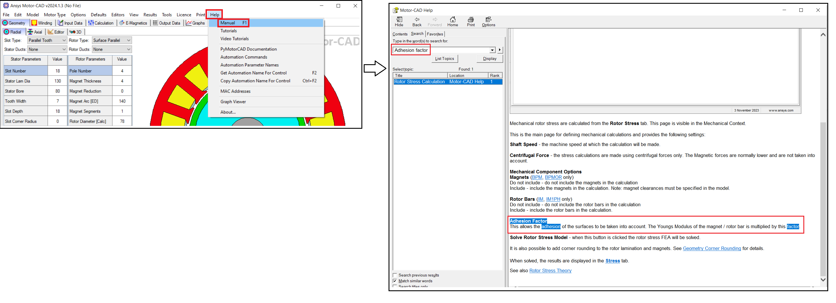
many of the parameters in MotorCAD include a simplified yet efficient way to account for physical effect of part interaction. the Adhesion Factor is one of those and accounts in a condenced way for the effect of the presence of a glue. The documentation describes its definition and use in the calculation.
regarding your design choice, unfortunately we can't provide educated comment as not being e-motor designers. Please try to discuss with a more experience e-motor designer or make some simulation studies to learn the sensitivity of your design to this paramenter (gap).
thanks -
October 9, 2024 at 1:52 pm
James Packer
Ansys EmployeeThanks for the question. The 'adhesion factor' is applied as a scaling factor to the magnet's Young's modulus for the magnet. If the adhesion factor is set to a low value, the magnet effectively becomes a mass loading on the rotor, without adding a stiffening effect. Because of the glue layer, this is normally a reasonable approximation, so we'd normally recommend a low value for this adhesion factor. You can also study the sensitivity of the stress to this, I'd expect a low sensitivity once you reach a reasonably low value for the adhesion factor.
One option to increase the fidelity of the calculation is to set the adhesion factor to 1.0, ensure that there is a small gap on both sides of the magnet ('Mag Gap Inner' and 'Mag Gap Outer' both non-zero), and setting the material in the rotor pocket (in the tab 'Input data->Materials', Rotor Pocket) to represent the adhesive material (for example 'Epoxy'). This allows the compliance of the glue layer to be modelled directly.
In any case, it is good to make sure that there is a gap modelled on at least one side of the magnet, as otherwise the FEA solution will represent a condition where the magnet 'glues' the two sides of the pocket together, giving an unrealistic increase in stiffness (because the Motor-CAD mechanical FEA solver is linear, gap opening effects are not included). I think from your comments, you are already doing this.
-
October 10, 2024 at 7:43 am
nkb221
SubscriberHi James,
Thank you for your response. Is there a tutorial on how to extend this to a full validation in ANSYS Mechanical?
-
October 10, 2024 at 8:39 am
James Packer
Ansys EmployeeThe best overview on this topic is probably the webinar that's available on demand at https://www.ansys.com/en-gb/webinars/developing-electric-machines-to-meet-durability-and-reliability-targets, which covers the analysis in Motor-CAD, and then moves on to the more detailed investigations possible in Mechanical.
-
- You must be logged in to reply to this topic.


- Three-Phase Voltage Imbalances in dual stator electric generator
- Link the Circuit to 3D Terminals
- Magnetic Dipole moment calculation
- Core Loss in ANSYS MAXWELL Eddy Current solution
- Error of Metal Fraction in Icepak Classic.
- The unit of theta in Is*sin(2*pi*fre*Time+theta-2*pi/3)
- simplorer-maxwell

-
4673
-
1565
-
1386
-
1231
-
1021

© 2025 Copyright ANSYS, Inc. All rights reserved.


