Accurately Simulating Modal Analysis for Honeycomb Composite Materials
-
-
November 22, 2022 at 6:28 pm
Mani Bhuma
SubscriberHello,
I am fairly new at Ansys and have been having some issues with accurately running simulations for a composite honeycomb material. Once I enter the orthotropic properties for the specific material I find the static structural results are fine; however, the modal results give ridiculous shapes as deformation results.
I have seen some of @peteroznewman posts on this topic, but am having some issues replicating the concepts.
I would appreciate help/feedback on this please!
-
November 23, 2022 at 1:49 am
peteroznewman
SubscriberHello Mani,
In Mechancial, right click on the Mesh branch and Clear Generated Data, then close Mechancial. In Workbench, save the Project. Then do File, Archive and save the .wbpz file. Upload that file (not the .wbpj file) to a sharing site such as Google Drive, OneDrive or Jumpshare. Copy the link to that file and paste it in your reply. Say what version of Ansys you are using in your reply. I will take a look at it.
Regards,
Peter
-
November 23, 2022 at 8:42 am
ErKo
Ansys EmployeePerhaps this helps also.
The actual absolute values of the displacement results (mode shape) do not mean anything in modal analysis, as these are scaled/normalised eigenvectors/mode shapes.
Only the frequency and the overall mode-shape are of interest (so if the mode shape is bending, torsional, etc), but not the absolute/actual values of the displacements.
See the help manual (search for mass normalized), and our course for more info on this /courses/index.php/courses/modal-analysis-in-ansys-mechanical/lessons/how-to-perform-modal-analysis-lesson-1-2/
Also this helps: https://www.eng-tips.com/viewthread.cfm?qid=83495
All the best -
November 23, 2022 at 11:17 pm
Mani Bhuma
SubscriberHi Peter,
I followed the steps you mentioned. Here is the link:
https://drive.google.com/file/d/1YULA2DUSUJsUvMUO-tehDswjwl7XVpNW/view?usp=share_link
I am using Ansys Workbench 2022 R1.
When you open the file you will see a 2 inch X 2 inch composite plate with an aluminum honeycomb center. My goal is to gather material information about the honeycomb core. In the future I will running a much bigger simulation with a larger composite plate. Due to the size of this new simulation it would be unreasonable to model the honeycomb core. So, using the material properties I find with this miniature simulation I will transfer the information to a model with 3 basic solid bodies. 2 rectangular solid bodies for the carbon fiber skins and 1 rectangular solid body for the honeycomb core.
Once I verify the static structural and modal results on this simulation is accurate would it be possible to extract information such as young's modulus in each axis from the honeycomb body for this purpose?
Best,
Mani
-
November 24, 2022 at 12:20 pm
peteroznewman
SubscriberHi Mani,
You mentioned orthotropic material properties in your original post, but when I look at your materials, they are all isotropic.
When I look at your Ansys project, you have modeled the hexagonal honeycomb cells using surface geometry and assigned a wall thickness and material properties for solid aluminum. By modeling it this way, you may not need an orthotropic material model. However, your model has not captured an important feature of honeycomb core, the double wall thickness created as a result of the manufacturing process. Foil sheets of thickness t are bonded together with strips of adhesive of width h and the strips of adhesive are staggered on the odd and even layers of foil. When that stack of foil sheets is pulled apart, a honeycomb cell is created, but notice in the figure below that some of the walls of the hexagonal cell have a wall thickness of t while others have a wall thickness of 2t.
Your model does not represent that.
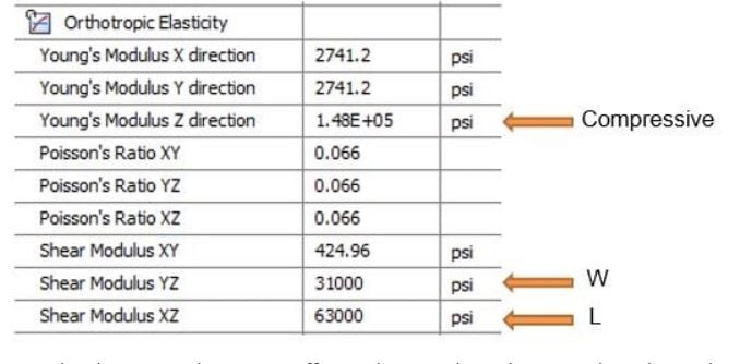
A simpler way to model a honeycomb core sandwich is to use orthotropic material properties. Instead of modeling the hexagonal cells with surfaces, the entire core is represented by a solid body assigned an orthotropic material. The manufacturer provides the critical material properties of this core on their webpage. The properties are orthotropic relative to directions in the core called L and W. The L direction is horizontal in the figure above, and that is the length of the foil sheets. The W direction is vertical and that is the direction the sheets were pulled to open up the cells. Once face sheets are bonded to the top and bottom of the core, and the sandwich panel has some bending applied, you would expect a higher modulus in the L direction because that is shearing the walls with the 2t thickness, while the lower modulus in the W direction is shearing the angled walls with the thickness t. Below is a copy of a manufacturers data sheet. Notice that the Shear Modulus in the “L” direction is about twice as large as the “W” direction. The other critical property is the compressive modulus.
Ansys Orthotropic material models require more constants than those three, but those are the critical ones.
Composite facesheets can also be orthotropic, but if many layers are stacked at multiple angles, the sheet can end up with nearly isotropic properties, especially if the laminar are fabric and not uni-directional tapes.
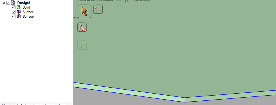
The surfaces representing the composites would be modeled coincident with the top and bottom faces of the solid core. Use Shared Topology so that the mesh of shell elements shares the nodes on the solid elements that mesh the core. This avoids using any bonded contact.
-
November 28, 2022 at 6:26 pm
Mani Bhuma
SubscriberHi Peter,
I originally attempted a solid body with orthotropic materials as you mentioned. Similarly, to the datasheet you provided I have the exact same datasheet of the material I am using. However, as you mentioned, the datasheet only provides three constants of the many. I tried to use an educated guess to estimate the other values, but I kept getting ridiculous mode shapes in the modal analysis. My solution to this issue was to recreate the composite with the honeycomb completely modelled, as I know the isotropic material the honeycomb itself is made of. Then, use the results of this new model to adjust the material values on the solid body until I got similar results. Please let me know if there is a simpler solution than this.
Thank you for catching that important feature I was missing in the honeycomb. Is there a way to model that into my simulation with surfaces?
Best,
Mani
-
November 28, 2022 at 8:55 pm
peteroznewman
SubscriberHi Mani,
You opened this topic with a statement that you were getting ridiculous mode shapes from an orthotropic material. I was curious to see those shapes, but you took the orthotropic material out when you shared your model so I have not yet seen what you meant by that. Will I get a chance to see that?
You moved on to explicitly modeling the honeycomb cells. You can assign double the thickness to those faces that need it.
You say you plan to use the results of the honeycomb cell model to adjust the values of the orthotropic core material until the results match. You make it sound simple, but what you are saying is actually complicated.
What loads and boundary conditions you will use on the two models? What result will you pull from each model?
There are nine material constants in the orthotropic material model, how will you adjust those nine numbers based on a comparison of the results between the two models? Will you keep the honeycomb vendor values constant? There is a constraint equation involving the nine constants that must be satisfied, so you are not free to choose values that don't satisfy the constraint. How will you incorporate the constraint equation in your value update method?
-
November 29, 2022 at 1:52 am
Mani Bhuma
SubscriberHi Peter,
Here is the link to the simulation of solid bodies made of orthotropic materials:
https://drive.google.com/file/d/1vdAKUp0dghMrUdfFji6ykdBO_ZZDjV8L/view?usp=share_link
In the honeycomb cells model, do I assign double the thickness of those faces by using the 'surface coating' feature?
Please correct me if I am mistaken in the following. Out of the nine constants, the vendor has provided three for me (Young's modulus Z direction, shear modulus YZ, and shear modulus XZ). Then, in each direction a constraint equation of E=2G(1+v) must be maintained. E is Young's modulus, G is shear modulus, and v is Poisson's ratio. Currently, in each direction there are two unknowns in the equation whether it is E and v or G and v. If I was able to extrapolate information on poisson's ratio in each direction I should be able to get the remaining material properties using the equation. Now, this is clearly the difficult part. I thought of running three separate static structurals where there is a fixed support and compressive force in each axis. Then, making estimated guesses on the poisson's ratios until I found relatively similar results in the honeycomb cell model and the solid body model. If I was to find a combination of poisson's ratios that satisify all three static structurals, I'd be quite confident with the material properties.
However, before I was able to test this theory, I received an issue with modeling the honeycomb cell model itself. As you may have seen in the file I sent, the modal results were unrealistic. I would appreciate any advice or suggestions on how I could model the solid body model accurately without the honeycomb cell model. From the link in the beginning of this message, are you able to see any missteps I took in this modelling approach?
-
November 29, 2022 at 12:06 pm
peteroznewman
SubscriberHi Mani,
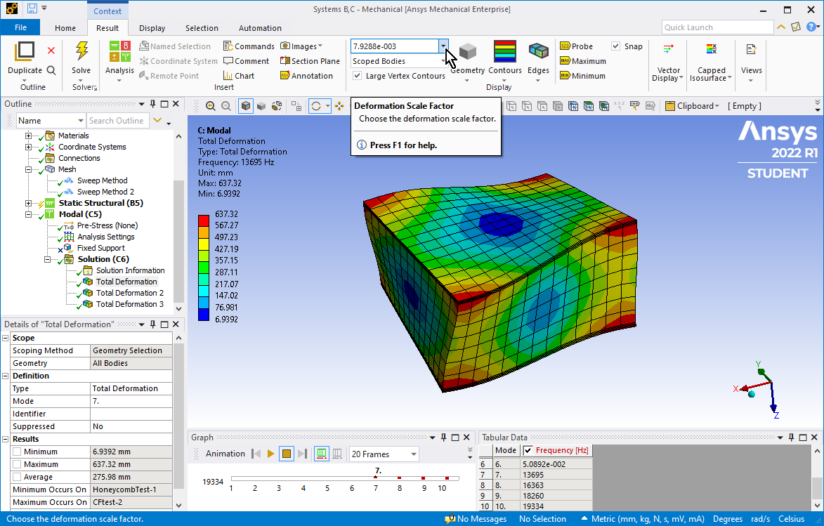
The solid orthotropic materials give a perfectly good mode shape. Did you turn down the Deformation Scale Factor as shown in the image below? Displacements in a Modal analysis are arbitrary, so you might need to turn this down until you get normal looking displacements.
I suppressed the Fixed Support and requested 9 modes instead of 6 modes. With no support, the first six modes are rigid body modes with no deformation and a practically zero frequency. Modes 7 and up are bending modes.
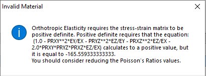
Orthotropic materials are not required to satisfy the Isotropic relation you showed above.
Orthotropic materials are required to satisify this requirement:
The way I would get the 2t thickness is by doing a split body on the two planes that bound a column of 2t faces so that you have separate bodies for the t thickness walls from the 2t thickness walls. In SpaceClaim, on the Workbench tab, use the Share button to have the mesh connect the separate bodies together.
I don’t think it is necessary to build a honeycomb cell model to get good orthotropic material constants. What would be more useful is if you can do a 3 or 4 point bending test on a physical honeycomb sandwich sample, or do a shear modulus test on a physical sample of the core.
One way to make the model solve faster is to replace solid elements on the face sheets with shell elements, however, you will have to do some work to align the material properties to a coordinate system. The reason is solid elements automatically align the material direction to the global coordiantes by default. However, shell elements automatically align the material direction to the element coordinates by default, and that can result in the material direction randomly pointing in different directions depending on how the face was meshed. You are almost required to override the default direction and define the material direction you want.
-
November 29, 2022 at 10:29 pm
Mani Bhuma
SubscriberHi Peter,
Thank you for the detailed response. I have a lot more clarity now!
Is there a reason you chose a very specific deformation scale factor of 7.9288e-3?
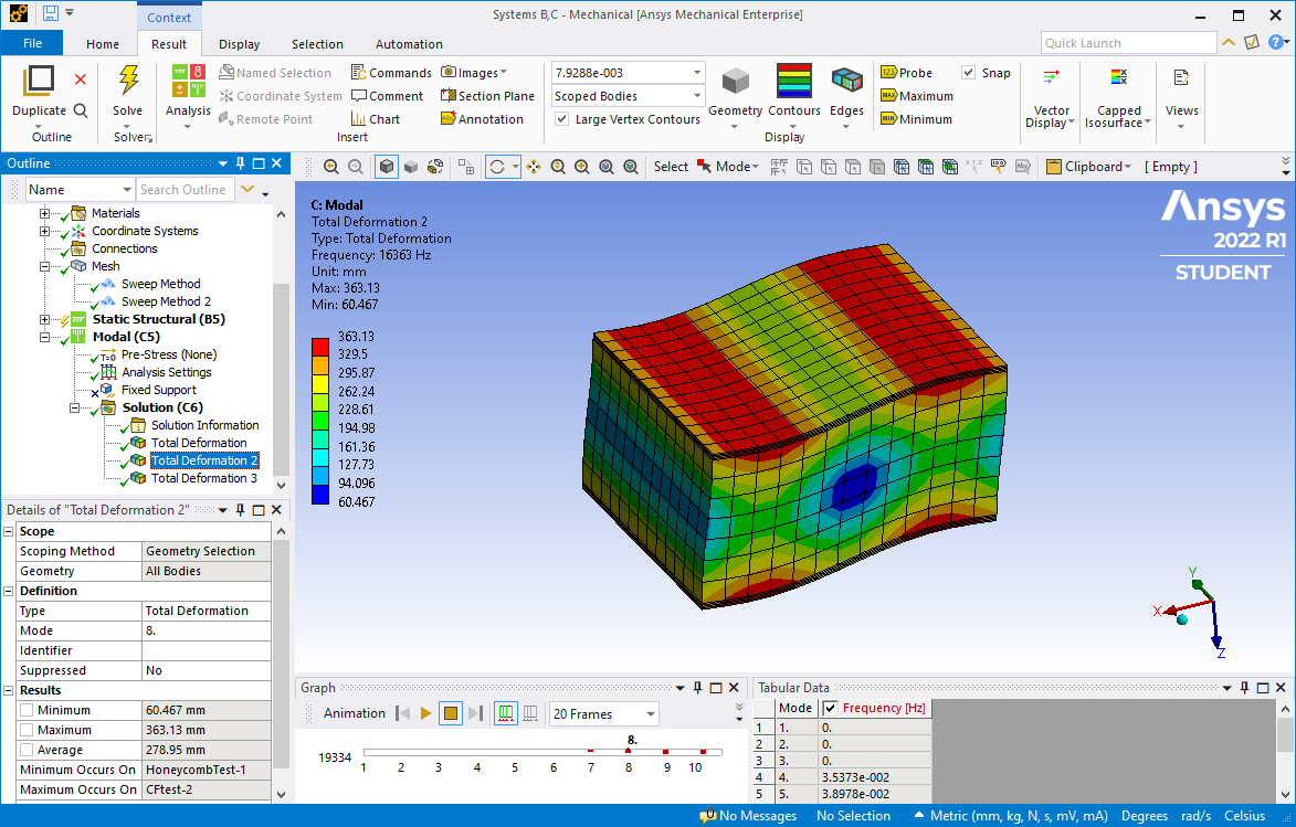
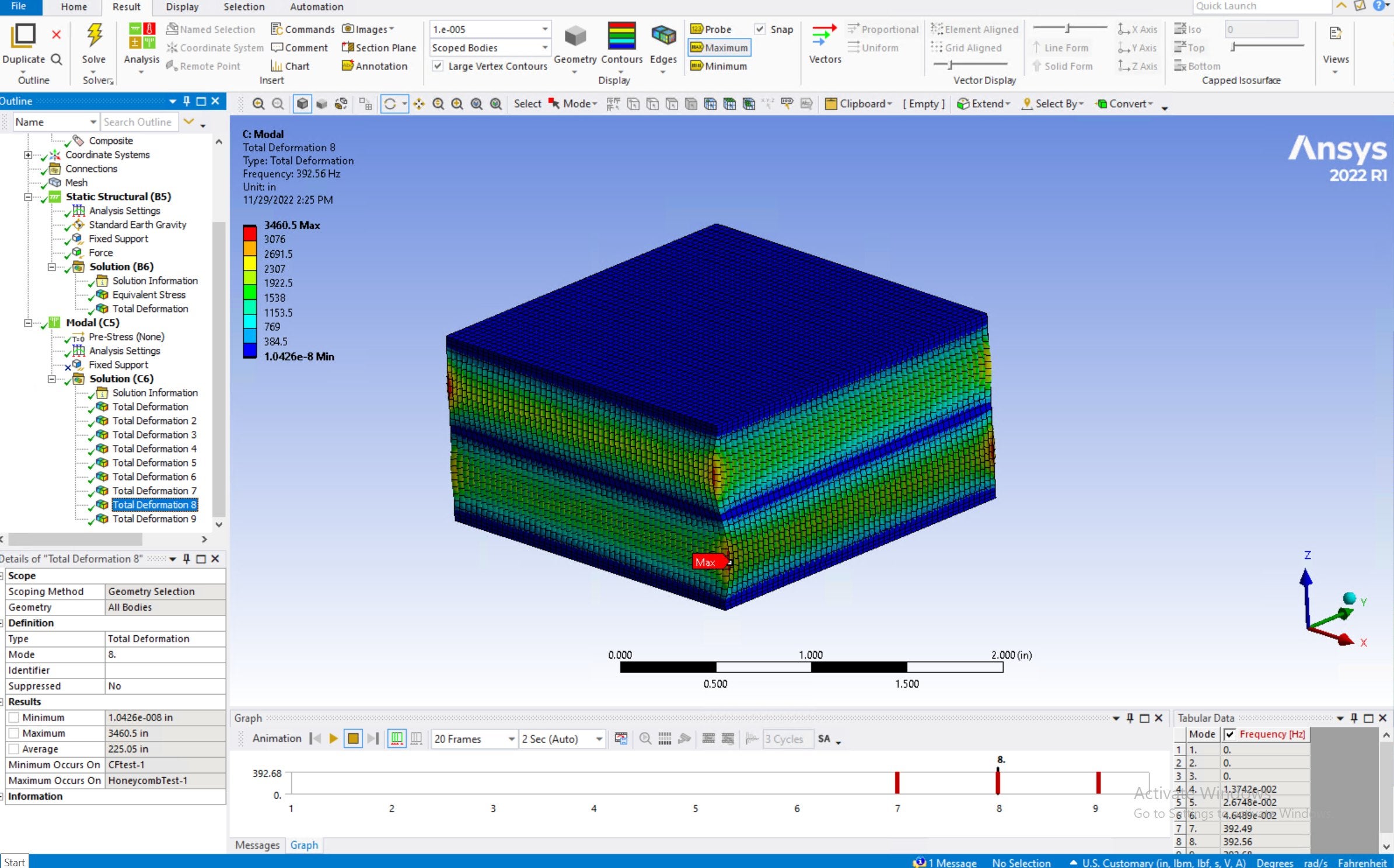
I reran my simulation to adjust the deformation scale and take a closer look at the results, but I found my results were quite different from yours. Did you change any of the material properties? I noticed you also used a couple 'Sweep Method' features in your mesh. Does this just increase the speed of the mesh, or does this significantly change the formation of the mesh? I attached images of my results below.
As you can see from the images, it seems the face sheets are not experiencing any deformation and the bending modes' frequencies are quite different from your results.
How would I use the results from a 3 point bending test to estimate good material constants in modal analysis?
Best regards,
Mani
-
November 30, 2022 at 12:37 am
peteroznewman
SubscriberAnsys Mechanical offers you an automatically calculated Display Scale Factor which is called Auto, Auto 0.5x and Auto 2x. I choose one of those that looked good. If the Scale Factor is too large, the display looks bad, which is what you were initially observing.
I couldn’t solve your mesh because it exceeded the Student License Limits, so I had to use larger elements. However, I still wanted 4 linear elements through the facesheet thickness. I solved using Linear element order. I don’t know why your deformed shapes are so different to mine. There must be a significant difference because my mode 7 frequency was 13.7 kHz while yours was 392 Hz so your and my materials have a dramatically different stiffness or density or both. Check what material was assigned to each layer.
If you have a physical test of a 3-point bending test, you will know the stiffness of the sample in lbf per inch of center deformation. You can build a model of the same test and tune the shear modulus until the model gives the same stiffness.
-
September 13, 2023 at 3:25 pm
Henning Eimstad
Subscriber@peteroznewman;
Quick follow-up regarding this topic.
When modeling composite materials, would you recommend using orthotropic properties on a solid plate or using the ACP module? Whats the difference and why would you use one over the other?
Thanks.
-
September 13, 2023 at 5:40 pm
peteroznewman
SubscriberHenning,
Are you talking about composite face sheets bonded to an aluminum honeycomb core? In that case, I recommend shell elements for the face sheets that share topology with solid elements that represent the honeycomb core. You would use orthotropic material properties for the composite laminate and orthotropic material properties for the honeycomb core. This assumes you can obtain the orthotropic material model for the composite laminate.
Copying a paragraph from an earlier post...
One way to make the model solve faster is to replace solid elements on the face sheets with shell elements, however, you will have to do some work to align the material properties to a coordinate system. The reason is solid elements automatically align the material direction to the global coordiantes by default. However, shell elements automatically align the material direction to the element coordinates by default, and that can result in the material direction randomly pointing in different directions depending on how the face was meshed. You are almost required to override the default direction and define the material direction you want.
If you don't have the orthotropic material properties of the laminate, but you know all the details of the stack of lamina: the material, orientation, thickness and stacking sequence, you can use ACP-Pre to create the material to give the correct properties to the shell element.
-
September 14, 2023 at 6:52 am
Henning Eimstad
SubscriberPeter,
Yes - I was talking about honeycomb core bonded to face sheets. I just found this arbitrary datasheet from Larcore - and it looks like it is quite common to give transversal and longitudinal rigidity in these datasheets.
Would you just make a sandwich like this then, with shared topology between the two surfaces and the solid in the middle? Could you also use surface coating instead of the two surfaces?
Thanks!
-
September 14, 2023 at 11:12 am
peteroznewman
SubscriberHenning,
A surface coating in Mechanical automatically creates shell elements on the element face that share nodes with existing elements. I have used it for coating with isotropic materials. I don’t know if you can assign a material direction the way you can with surface bodies. Try it and see.
The table you show for a Lacore panel represents the rigidity (EI) of the panel made from a sandwich of a specific honeycomb core density and thickness and a specific facesheet material and thickness. That is different from the properties of the facesheet alone. To use that data in Ansys, you would separate the E from I and then break I down to a thickness because those are the inputs needed in Ansys, there is no input for EI. Then you would use just a surface to represent the sandwich panel and assign that material along with the thickness of the panel. That will create a model that will have the correct stiffness, but you won’t know the stress in the individual layers in the sandwich. You won’t know the shear stress in the core or the tensile stress in the facesheet.
-
September 14, 2023 at 2:28 pm
Henning Eimstad
SubscriberPeter,
If I understand you correctly, using those rigidity (EI) numbers is sufficient information - but you need to do some manual juggling work with the numbers. If the honeycomb panel (sheet + honeycomb + sheet) is 6 mm, the solid geometry in ANSYS does not necessarily need to be 6 mm? Could you please give a simple example using some arbitrary numbers and plate size (and thickness)? Would be really helpful to see if I understand it correctly. If the sheet panels are isotropic, and I have the data rigidity data available for the honeycomb core only - could I make it as shell (isotropic) + solid (orthotropic) + shell (isotropic) with shared topology?
Thanks
-
September 15, 2023 at 1:39 pm
peteroznewman
SubscriberIf you have rigidity data for a honeycomb core sandwich, that data already includes the stiffness of the core and two facesheets bonded to the core. In that case, make a surface body, assign the true thickness of the panel and create a material for that surface that has a value of E so that EI equals the value from the datasheet.
-
- The topic ‘Accurately Simulating Modal Analysis for Honeycomb Composite Materials’ is closed to new replies.


-
4838
-
1587
-
1386
-
1242
-
1021

© 2026 Copyright ANSYS, Inc. All rights reserved.


