TAGGED: evanescentwave, Lumerical-FDTD, nanoparticles, TFSF
-
-
December 12, 2024 at 11:16 pm
katsuya2
SubscriberI am working on simulating the polarization-dependent absorption cross-section of a gold nanorod (AuNR) using Ansys Lumerical FDTD. The AuNR is excited by the evanescent field generated through prism-based total internal reflection (TIR).
Here is the setup of my simulation:
- A total-field scattered-field (TFSF) source is used with a 60-degree incident angle. The light first propagates through the air and then enters a prism (glass, n=1.52).
- The prism is placed on a glass substrate coated with a 140 nm indium tin oxide (ITO, n=1.96) layer.
- A single AuNR is deposited on the ITO layer and immersed in water (n=1.33).
- At the substrate interface, I expect an evanescent field to excite the plasmon resonance of the AuNR.
My goal is to calculate the absorption cross-section of the AuNR as a function of the polarization angle relative to its long axis.
A key challenge I face is the large disparity in scales: the prism is on the microscale, while the AuNR is on the nanoscale. Is it feasible to include both the prism and the AuNR in a single simulation domain? If so, how should I approach setting up such a simulation to ensure accurate results?
I would greatly appreciate your insights and guidance.
Best regards,
Katsu -
December 18, 2024 at 7:48 pm
katsuya2
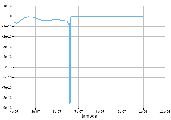
SubscriberHi, after fixing the source into the FDTD domain, I got the following result for absorption cross-section.

From the monitor, tfsf source reached the particle and provided some enhancements on the tip of gold nanorods.
After the peak position 660 nm, the rest of wavelength has 0 cross-section. I don't understand what's going on here.
I guess the glass and ITO substrate might have some interferences with each other.
My idea is to get rid of the prism and air part and put the source in the glass to avoid the interefenrece.
This still allows us to realize total internal reflection at the interface between ITO and glass to excite the plasmon. |
Please let me know what you think.
Best,
Katsu
-
December 19, 2024 at 7:22 pm
katsuya2
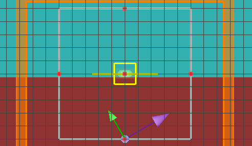
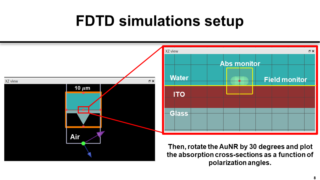
SubscriberHi, I simplified the geometry as follows:

I want to realize the total internal reflection at the interface between ITO and water.
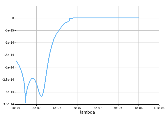
As a result, I got the following absorption cross-section.
I performed 4 AuNRs by rotating 30 degrees and observed a constant 445 nm peak and 660 nm cutoff.
However, I still see the peak at around 530 nm (I believe this is a transverse mode of localized surface plasmon resonance), and it changed as a function of the polarization angle.
Do you know why I saw the constant absorption cross-section cutoff?
I'd appreciate your response.
Best,
Katsu -
December 27, 2024 at 7:26 pm
Amrita Pati
Ansys EmployeeHi Katsu,
I apologize for the delay in getting back to you! We are a bit understaffed this month. It can be a bit tricky to setup the TFSF source. I believe the first thing we can do is to make sure that the TFSF source has been setup correctly. You can disable the gold nanorods and then run the simulation and see what the absorption/scattering cross-section is. They should be 0 without the scatterer. It will be hard to predict the reason behind the peak at 530 nm (if it is physical/numerical artifact) without having a look at the simulation itself. Is your simulation based on any paper?
Regards,
Amrita
-
- You must be logged in to reply to this topic.


-
4618
-
1530
-
1386
-
1210
-
1021

© 2025 Copyright ANSYS, Inc. All rights reserved.


