-
-
July 26, 2022 at 6:38 pm
patrickm7995
SubscriberI have a thin plate with the bottom surface receiving solar flux, and the other surfaces being fully transparent and the inside of the geometry being air with very low (1e-5) density.
This bottom wall was set to 0 transmissivity and 0 absorptivity for this case, so it was expected that the solar radiation coming in (1377 W/m2) would be split between reflectivity in the IR and visible, 688.5 W/m2, which occured.
However, the absorbed visible solar flux map was also showing a value, which was unexpected. The absorbed IR was as expected, 0 W/m2.Â
Does anyone have any reasons this may be occuring? Thank you.
-
July 28, 2022 at 6:13 pm
SVV
Ansys EmployeeHi,
Can you please check your settings again?
Please note absorbed visible solar flux is not evalueted for opaque surface.
Â
-
July 28, 2022 at 7:11 pm
patrickm7995
SubscriberThank you for your reply. Sorry, I am confused: opaque surfaces do not have absorbed solar flux?
-
-
October 13, 2022 at 3:50 am
li can
Subscriberi have the same confusing , how to set opaque surface condition to absorb solar flux ?Â
-
- The topic ‘
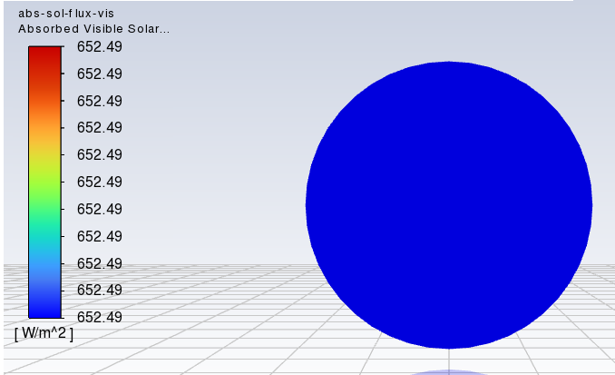
Absorbed Visible Solar Flux — Unexpected Results?’ is closed to new replies.
- air flow in and out of computer case
- Varying Bond model parameters to mimic soil particle cohesion/stiction
- Eroded Mass due to Erosion of Soil Particles by Fluids
- I am doing a corona simulation. But particles are not spreading.
- Centrifugal Fan Analysis for Determination of Characteristic Curve
- Guidance needed for Conjugate Heat Transfer Analysis for a 3s3p Li-ion Battery
- Issue to compile a UDF in ANSYS Fluent
- JACOBI Convergence Issue in ANSYS AQWA
- affinity not set
- Resuming SAG Mill Simulation with New Particle Batch in Rocky
-
4097
-
1487
-
1318
-
1156
-
1021
© 2025 Copyright ANSYS, Inc. All rights reserved.