TAGGED: #fluent-#cfd-#ansys, #heat_exchanger, fluent, fluent-mesh
-
-
March 15, 2024 at 7:50 pm
Ashen Perera
SubscriberHi ,
I am concerned mainly about the shell side flow and I would like to model the tubes as solid cylinders with a fixed wall temperature of 450K I would like to know how can i acheive this ( coupled interfaces among the solid and the shell fluid volume has been made )
This is how i did it but i am not sure about my approach ( shell side I need fluid and tube side as a solid cylinder )
- The interfaces are left as coupled ( wall , wall - shadow , src , trg )
- Cell zone allocation change to solid for the tubes
- Temperature of 450K given to the inlet and outlet ( my thinking is that due to perfect conduction the walls will also be at 450K i need the wall of the tube to be at 450K .
I would also like to know if I can take the approach of just assigning a fixed wall temperature to the tube side (basically a hollow cylinder so that the wall adjacent to the shell is kept at 450K)
Thanks in advance ,
Ashen
-
March 18, 2024 at 11:33 am
Rob
Forum ModeratorOK, there are a few options.
- Heat source in a solid (meshed) tube
- Heat flux/temperature/convection on the "other" side of the tube wall
- Heat flux/temperature/convection on the wet side of the tube bounding the shell side fluid
All are valid, I'd probably go for convection on the wet wall, as that minimises the mesh requirements and probably good enough with some care.
-
March 19, 2024 at 2:34 am
Ashen Perera
SubscriberI also went with the third option where the interface among the shell and tube is given a fixed temperature . But the solution doesn’t converge at the expected value of the pressure, what factors should I be concerned about if this the case (mesh quality is good , solution converges but the value is wrong compared to literature ), the temperature increase is in fair margin but the pressure drop results show a significant difference with that in the literature.
-
March 19, 2024 at 11:06 am
Rob
Forum ModeratorWhat material properties did you use?
-
March 19, 2024 at 11:22 am
Ashen Perera
SubscriberHi , for the solid wall that separates the aluminum solid fluent properties used (named selection is done to select the walls as the cylinder is not meshed ) , so basically for the fluid water properties (piece wise linear is used).
-
March 19, 2024 at 11:42 am
Rob
Forum ModeratorOK, so water, and water's density is pretty much constant for forced convection devices. Next step is to look at the mesh. Note, the outlet pressure you set, inlet is then calculated relative to that so please confirm you're comparing pressure relative to that with the same in the theory/experiment.
-
March 19, 2024 at 12:00 pm
Ashen Perera
SubscriberOkay so the mesh quality is (maximum skewness is at 0.7898) , I think I should increase it further by decreasing the element size from 2.00 mm further downward in steps of 10% . I haven't added inflation , also the outlet pressure is at zero gauge pressure my literature states that there pressure drop was at 2000 Pa I get around 4000 Pa , also there are negative pressures recorded but after some runs it converges to zero as well . Shall I decrease element size and analyse further as I don't understand what's wrong in my pressure drop
-
March 19, 2024 at 12:03 pm
Rob
Forum ModeratorPlease post some results.
-
March 19, 2024 at 3:39 pm
Ashen Perera
Subscriber -
March 19, 2024 at 3:40 pm
-
-
March 19, 2024 at 3:42 pm
-
March 19, 2024 at 4:22 pm
Ashen Perera
SubscriberHi ,
I have attached a image of the centerline pressure contour ( I suspect the high value of pressure present in the inlet area , according to the literature i am following the value should be around 2351 Pa - a study done on a similar type heat exchanger) : I have conducted grid independence yet but I think thats the next step I am gonna do by decreasing the element size from 2mm and down.
Thanks in advance for any help you can offer to figure this error
-
March 19, 2024 at 4:25 pm
Rob
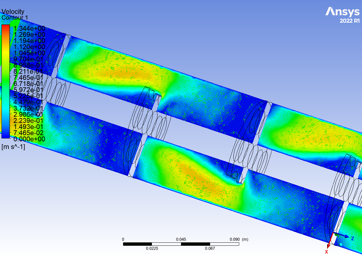
Forum ModeratorUse Fluent, and zoom in around the baffles. You may need to look at the velocity field too. Possibly compare node values on & off.
-
March 19, 2024 at 4:36 pm
-
March 19, 2024 at 4:42 pm
Rob
Forum ModeratorIn Fluent you can show the smoothed results or the cell values. That makes it easier to see whether the mesh is sufficient to resolve the flow.
-
March 19, 2024 at 5:01 pm
-
March 19, 2024 at 5:16 pm
Rob
Forum ModeratorPotentially you need to refine the mesh, ie resolve the gradients; hard to say from the images and there's a reason I pointed out the screen shot button! There's also model error. Have a look in the Fluent training in Learning, the things to check are probably in there.
-
March 19, 2024 at 5:20 pm
Ashen Perera
SubscriberHi ,
Thanks for the advice , by model error do you mean that you see a model error in the solution i have obtained ?
TIA
-
March 19, 2024 at 5:23 pm
Rob
Forum ModeratorNo, it's something to understand & check. The classic example (which is covered in the Fluent User's Guide) are the turbulence models: most suffer from limitations of some sort which is why there are a few to choose from. Read https://ansyshelp.ansys.com/account/Secured?returnurl=/Views/Secured/corp/v241/en/flu_ug/flu_ug_sec_turb_choosing.html for more information.
-
March 19, 2024 at 5:28 pm
Ashen Perera
SubscriberHi ,
oh right I used turbulence models as suggested by the literature review I did , also can i know what you mean by resolve the gradients. Additionaly just want a comment abt my refinement strategy ( if i used 2 mm as a start i plan on reducing it by 1.3 times each time and studying the pressure drop ). Also the tiny osscilatory movement in the residuals and it settling could be due to what reason.
TIA
-
-
March 19, 2024 at 5:36 pm
Rob
Forum ModeratorSize is relative - look at how well you're resolving the flow. Residuals like that can mean the flow is transient, hence you needing to review all results and not just single values or graphs.
-
- The topic ‘About modelling the tube side flow as a solid cylinder’ is closed to new replies.


-
5024
-
1714
-
1387
-
1248
-
1021

© 2026 Copyright ANSYS, Inc. All rights reserved.

.jpg)
.jpg)


.jpg)


