-
-
September 27, 2022 at 2:27 am
2212296
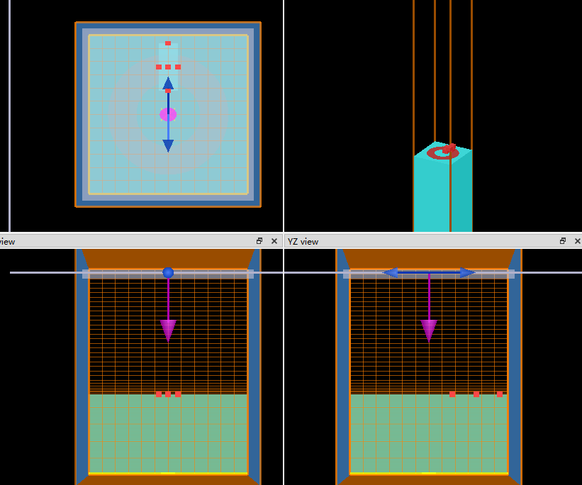
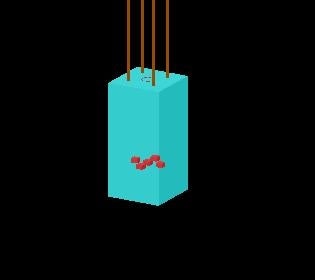
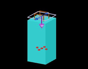
Subscriberhi everyone, I am running a simulation of a split resonator.
The wavelength is 100um-300um (1Thz-3Thz).
The aluminum is set as a lossy metal with a conductivity of σ = 3.56e+7 S/m. The ring thickness is 500*nm
The refractive index of the substrate is 3.4 and the thickness is 500*um
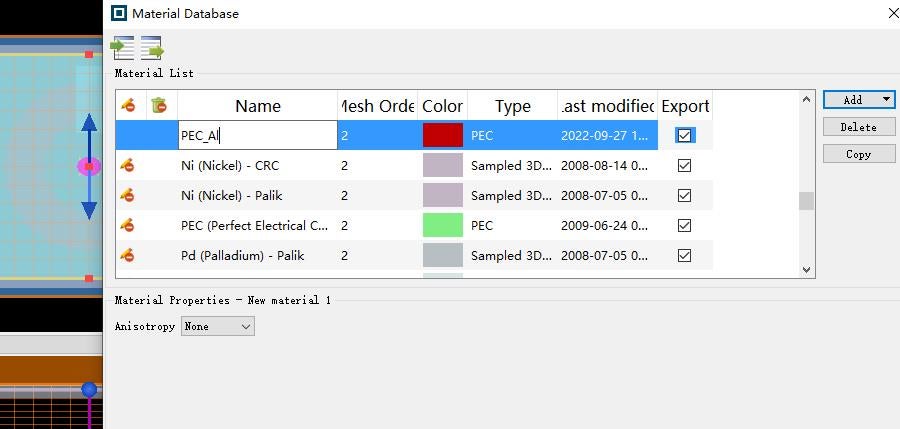
Followed the advice of the forum engineer, talk about metal aluminum setting pec
But,there are still many problems.
-
September 27, 2022 at 2:33 am
2212296
Subscriberswitchtolayout; selectall; deleteall; clear; clc; switchtolayout; nm = 1e-9; um = 1e-6; fs = 1e-15; lambda_start = 100*um; lambda_end = 300*um; p = 100*um; # Al_ring addring; set("name","al_ring"); set("x",0); set("y",0); set("inner radius",20*um); set("outer radius",38*um); set("z min",0); set("z max",200*nm); set("theta start",0); set("theta stop",0); set('material','PEC_Al'); # etch addrect; set('name','etch'); set('x',0); set('x span',12*um); set('y',30*um); set('y span',30*um); set('z min',0); set('z max',200*nm); set('index','etch'); # sub : sapphire addrect; set('name','sapphire'); set('x',0); set('x span',p); set('y',0); set('y span',p); set('z min',-500*um); set('z max',0); set('index','3.4'); ## simulation addfdtd; set("dimension",2); # 1 = 2D, 2 = 3D set('simulation time',4000*fs); set('x',0); set('x span',p); set('y',0); set('y span',p); set("z min",-520*um); set("z max",800*um); set("mesh accuracy",2); # set boundary conditions set("x min bc","periodic"); #这里用序号而不是Periodic的名称 set("y min bc","periodic"); set("z min bc",1); set("z max bc",1); # Source addplane; set("name","Source_y"); set("injection axis","z"); set("direction","Backward"); #set('phase',180); #rcwa:delta0=90 #set('phase',180); set("polarization angle",-90); set("amplitude",1); set('x',0); set('x span',p); set('y',0); set('y span',p); set("z",780*um); set("wavelength start",lambda_start); set("wavelength stop",lambda_end); #monitor #T_point addpower; set("name","T_point"); set("monitor type",1); # Point set('x',0); set('y',0); set("z",-510*um); set("override global monitor settings",1); set("frequency points",200); ## T addpower; set('name','T1'); set("monitor type",7); # 2D z-normal set('x',0); set('x span',p); set('y',0); set('y span',p); set("z",-510*um); set("override global monitor settings",1); set("frequency points",200); # time_monitor addtime; set("name","time"); set("monitor type",1); # point set('x',0); set('y',0); set("z",-510*um); run; f = getdata('T1',"f"); T = transmission("T1")*(-1); plot(f/1e12,T,"f(THz)","T_Power"); -
September 27, 2022 at 2:36 am
-
September 27, 2022 at 2:37 am
2212296
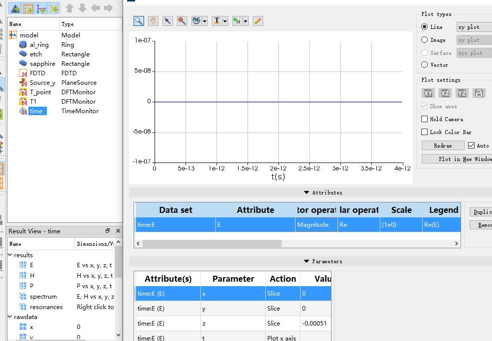
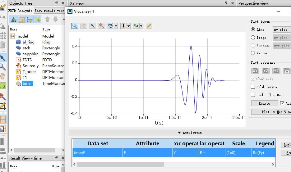
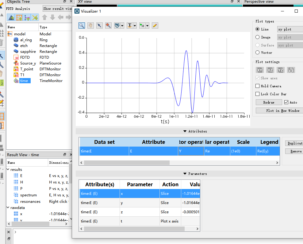
SubscriberThe time monitor did not detect any signal
-
September 27, 2022 at 2:39 am
2212296
SubscriberOh,sorry,the ring thickness is 200*nm -
September 27, 2022 at 4:17 pm
Guilin Sun
Ansys EmployeeThere are several issues in your scripted simulation file:
1: the substrate should be included for a small portion, like a fraction of wavelength (when no SPP). Currently you are simulating the substratge suspended in air, which forms a cavity;2: the distance from source to the up surface is too long. A fraction of wavelength is good.
3: you used periodic boundary conditions but the substrate is not large enough to be outside of the periodic BCs. FDTD is a discrete method that ExEyEz and HxHyHz are not collocated:
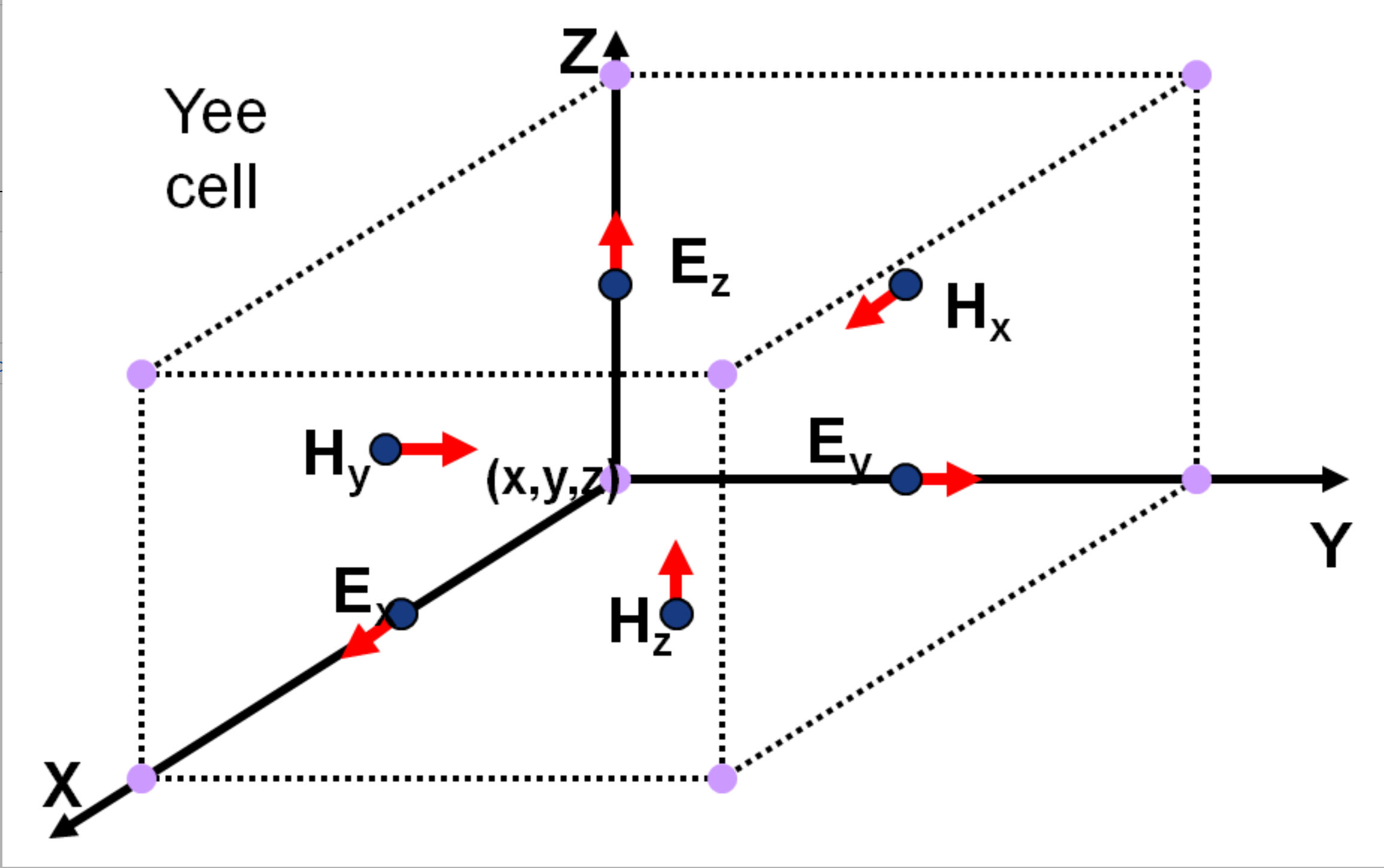
Therefore you will need to extend the substrate to outside of the PBC.
You current settings and PEC material use much less memory, but the long distance and THz simulation needs longer simulation time to have the pulse propagate to the bottom.
-
September 28, 2022 at 12:20 am
-
September 28, 2022 at 12:35 am
-
-
September 28, 2022 at 12:16 am
2212296
SubscriberHi, thanks for your reply.
1: the substrate should be included for a small portion, like a fraction of wavelength (when no SPP). Currently you are simulating the substratge suspended in air, which forms a cavity;
What does it mean? How to set it right?
3. You used periodic boundary conditions but the substrate is not large enough to be outside of the periodic BCs. FDTD is a discrete method that ExEyEz and HxHyHz are not collocated:
Solution: Make the substrate xy area larger than the simulation range?
-
September 28, 2022 at 12:29 am
Guilin Sun
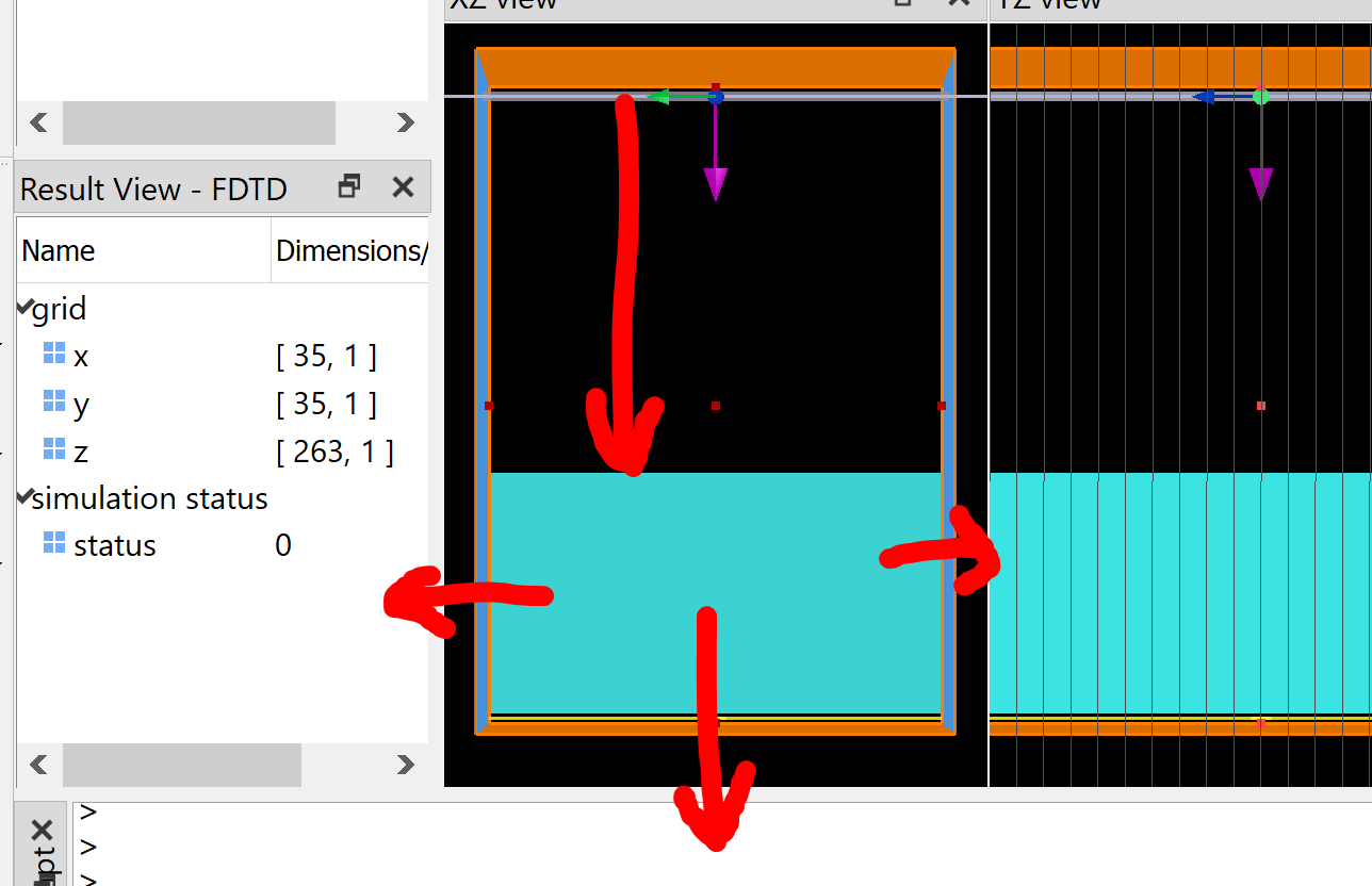
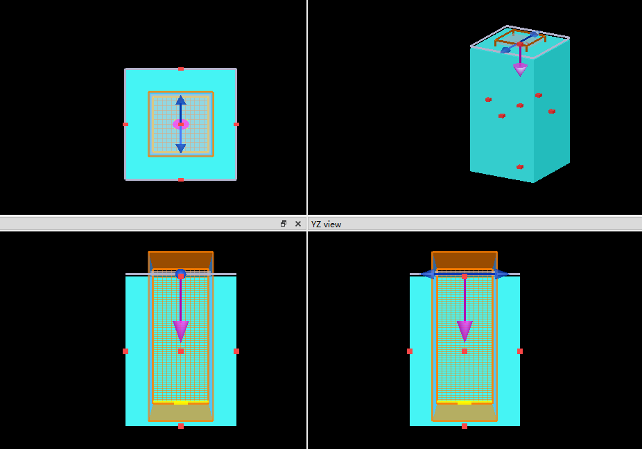
Ansys EmployeeA1: If you think it is mandatory to include the whole substrate in the simulation, you will need significant simulaiton time to count on the multi-reflections. Since the substrate is relatively thick, I think it is reasonable to siulate a small portion of it. The lower air/substrate interface merely introduces small refleciton loss.
I have illustrated how to do this in the screenshot and description.
A3: please refer the screnshot to expand the substrate in periodic directions.
-
September 28, 2022 at 12:42 am
-
-
September 28, 2022 at 12:45 am
Guilin Sun
Ansys Employee-
September 28, 2022 at 12:52 am
2212296
Subscriberyou mean: no need to thicken the substrate
-
September 28, 2022 at 12:55 am
-
-
September 28, 2022 at 8:20 pm
Guilin Sun
Ansys EmployeeYes, but if there is no other structure inside the susbtrate, you can further reduce FDTD Zmin. Only when there is strong SPP that penetrates far you need large space to deal with it. Using smaller simulation length can save time. As a rule of thumb, each side can have half-wavelength distances, or even smaller in most cases.
-
September 29, 2022 at 12:06 am
2212296
SubscriberBut I still need the light to pass through the 500um substrate (0um to-500um) The monitor is placed at -500um
-
September 29, 2022 at 12:09 am
-
-
September 29, 2022 at 3:08 pm
Guilin Sun
Ansys EmployeeMaybe it is not clear for you when I suggest to simulate portion of the substrate. If you want to include it, it is ok. But you will need much longer simulation time to make sure the signal due to multiple reflections decays completely in the device. Currently the time monitor only recorded the first refracted singal.
You can move the monitor to a closer location;
what value do you expect the maximum in the time monitor? if the signal has been absorbed/diffracted/scattered through the way, it should not reach the source magnitude.
Maybe you need to step back, and think how this device works and what the physics it has to obey. Please make sure the time-domain simulation is complete, and in your case I guess the autoshutoff min 1e-5 is not small enough.
I still woi=uld suggest you to simulate a small portion of the substrate, and check the result to see if it is expected, such as the time signals, the reflection R and transmission T (power quantities) in frequency domain, steady state. You may refer some online edu vidoes.
https://optics.ansys.com/hc/en-us/sections/360007813194-FDTD100-List-of-videos
-
October 2, 2022 at 7:40 am
2212296
SubscriberA rule of thumb is that we want there to be a distance of at least half a wavelength of
uniform material in front of the PML.
Since we will be simulating a wavelength up to 0.7 um, we want to measure a distance of at least 0.35 um of air above the structure and glass below.I saw this above. This means that if the wavelengths used are very large (100-300um), there will be more air layers above the aluminum film.(at least half wavelength :150um)
There is also more air layer below the substrate (at least half wavelength :150um)
-
-
October 3, 2022 at 9:45 pm
Guilin Sun
Ansys Employee" we will be simulating a wavelength up to 0.7 um"
"the wavelengths used are very large (100-300um)"
Not sure exactly what wavelength you are talking. Related issues have been discussed various times in different posts.
Since the background material is lossless, the monitor location does not affect the transmitted power;
you can place the monitor anywhere you want, as long as you know exactly what the result means to you.
Once again, the distance between PML and the device is to prevent any possiblility that the near fields interact with PML. If there is no local neaar fields such as non-rdiative, evanescent waves or SPP, the distance can be smaller.
-
- The topic ‘About Aluminum Ring Transmission Spectrum’ is closed to new replies.


-
4597
-
1495
-
1386
-
1209
-
1021

© 2025 Copyright ANSYS, Inc. All rights reserved.

