-
-
July 10, 2019 at 6:32 am
daveberutu
SubscriberHi Everyone
I'm also have similiar problem. Maybe some of you will succed from this solution /forum/forums/topic/solver-pivot-warning/ . But for mine, this brings me nowhere. I'm have tried all the solution given but still can't solve the problem
This Message Shows after I run a solver :
A solver pivot warning or error has been detected in the UY degree of freedom of node 111607 located in Surface Body. This is usually a result of an ill conditioned matrix possibly due to unreasonable material properties, an under constrained model, or contact related issues. Check results carefully. You may select the offending object and/or geometry via RMB on this warning in the Messages window..
Your help will be much appreciated
-
July 10, 2019 at 2:37 pm
-
July 11, 2019 at 3:13 am
-
July 11, 2019 at 3:34 am
Sandeep Medikonda
Ansys EmployeeIf you think it is the contact. Insert an Initial Contact Tool and make sure all contacts are closed. See the help
Look at your Newton-Raphson residuals
Perform a modal analysis and identify 0 frequency modes. The suggestions have already been provided in the link I shared above.
-
July 11, 2019 at 4:19 am
daveberutu
SubscriberI'm sorry but I'm still not understand how to disappear the gap. Maybe you can give the recomendation & spesific solution for my case.
And after I run the solver, I get the different error & warning but in the same issues. I don't know what's wrong with my model
-
July 11, 2019 at 10:49 am
jj77
SubscriberYou have a multi-body part thus the mesh at the split (along the length) will be connected hence no need to have a bonded contact.
Other than that switch off (set to Off) the Pivot Checking (under Analysis Settings) see how the model behaves. It is a very slender model so I would not be surprised if it might struggle. Also include more substeps to ramp the loads up - if it is still too much try switching of the loads and activate them one at a time to see what is causing the most sever problems.
Have in mind that large deflections is off - once you get this to run, activate it to see if this has an impact on results.
-
July 12, 2019 at 4:13 am
daveberutu
SubscriberThank you for the advice, but unfortunately it still doesnt fix the problem, moreover the new warning appear.
I don't know. I've increased the substep, set off pivot checking, delete bonded connection, but still doesnt give an impact
Do you think my model has wrong from the beginning? Or there is another way to model this tubing to make the calculation simpler.
-
July 12, 2019 at 4:57 am
peteroznewman
SubscriberPlease read the ANSYS Help on the PIPE288 element.
The geometry for this element is a line body, but the element creates a pipe cross section that can have internal and external pressure applied.
Another idea is to stabilize the far end of the pipe where the force is applied. You could add a displacement support that would prevent lateral motion in X and Y while leaving free longitudinal motion in Z.
-
July 12, 2019 at 5:58 am
jj77
SubscriberDefinitely consider pipe elements because such a structure is suitable for this. See this for more details on that.
https://www.ansys.com/en-gb/blog/ansys-pipe-simulation -
July 12, 2019 at 9:50 am
daveberutu
SubscriberThank you Mr. peteroznewman, Finally the solver can run smoothly eventough there is something weird on the results. The maximum stress happen on the connection and i think that's weird and maybe something was missing. Does anyone know which part in my connection that make it wrong?
thanks for the advice mr jj77. I've tried the line body first before in the shell mode. But there is some length limitation in the line body so the mode can't suit my model. My actual model is 6200 ft on length even shell mode can't accomodate it so i decided to break up tubing into 4 part in the different file
-
July 12, 2019 at 10:31 am
jj77
SubscriberNever heard of that. Then one can split the line-body into several line bodies (say 10 in DM) and merge them in a multi-body part.
-
July 12, 2019 at 11:50 am
peteroznewman
SubscriberDave, you have a fixed support around the entire circular edge that is part of a face that has a pressure applied. That means the face moves due to the pressure but the edge can't move and that causes the weird stress.
Use symmetry to resolve this issue. You already sliced your pipe in half. Slice it in half again to get a quarter pipe. Apply a Symmetry condition to the two slicing planes which will remove 3/4 of the pipe and you will only mesh 1/4 of the pipe circumference. Now delete the Fixed Support and use a Z=0 displacement condition. The two symmetry planes will control X and Y motion, while allowing to top edge of the pipe to expand with pressure unconstrained like the rest of the face and there will be no weird stress.
Since you have reduced the geometry to 1/4, you can use 4 times more elements around the remaining circumference to get a smoother curve of the pipe without increasing the solution time.
If you go to the pipe288 element, you won't have a weird stress problem because there is only a vertex at the top, and the pipe will freely expand there since that is solved inside the element.
-
July 13, 2019 at 7:40 am
daveberutu
SubscriberNo mr peteroznewmaan. The weird stress happen on the connection 2 half pipe parts, not on te fixed support. I think something's wrong is on the connection.
Thank you mr jj & Mr peteroznewman, I'll try using line body once more. And my last question I think
1. How I can split several line body and make it as multipart because max line body I only can make 1550 on length
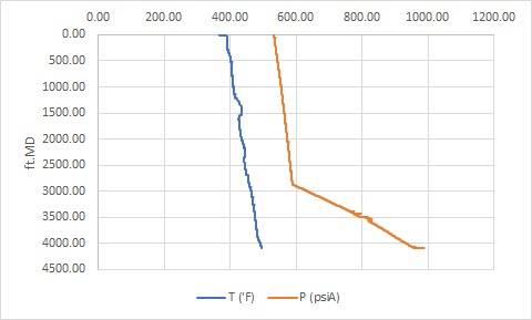
2. How to modelize this external pressure using function. because There is 2 line function from this graph in the different depth interval?
-
July 13, 2019 at 1:30 pm
peteroznewman
Subscriber -
July 13, 2019 at 1:37 pm
daveberutu
SubscriberOKay everyone, for now i will modelling my model with 2 method, line in body & using symmetrical in parallel and find which method can give the best result
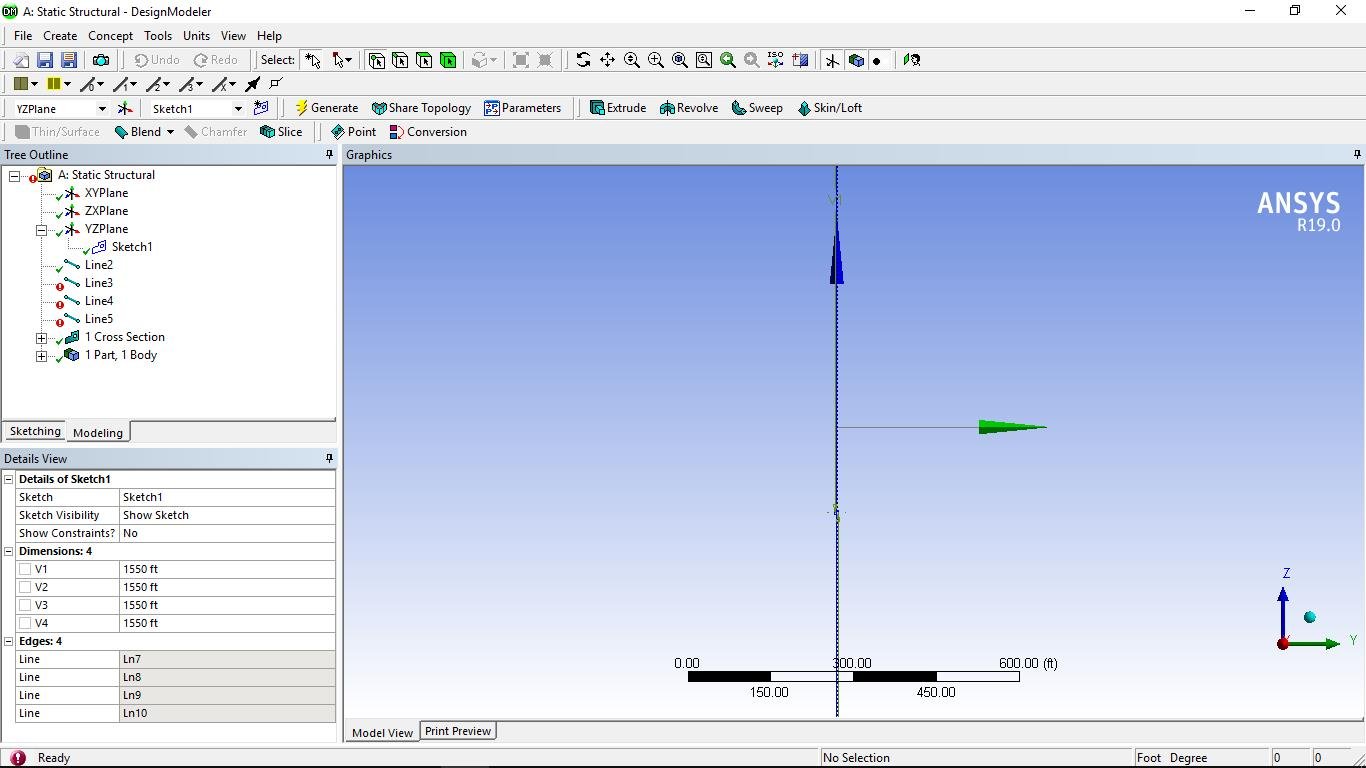
For line in body, I have difficulty to make 6200 part tubing & there is 2 function load line along the tube
For symmetrical method, I don't know why i can't choose the low boundary & high boundary with face & edge. It also not work on the edge in the shell mode

How I can solve this problem?
-
July 13, 2019 at 2:30 pm
peteroznewman
SubscriberI have attached an ANSYS 19.0 archive that has the 6200 ft long pipe in the -Z direction. I don't know how to create the APDL code to create pressure as a function of Z coordinate, but perhaps jj77 can help.
In Mechanical, under Geometry you can see the Beam listed and Model Type can be switched from Beam to Pipe. When I do this and solve, the Solution Output shows that Mechanical is automatically setting some Keyops on this element as shown below.
 *** WARNING ***                         CP =       0.562   TIME= 10:01
 PIPE288/289 element 1 with thin pipe formulation (KEYOPT(4) = 1)
 references pipe section ID 1 which has a radius to thickness (R/t)
 ratio of 30.  If the R/t ratio < 50, please use the thick pipe
 formulation (KEYOPT(4) = 2).  Checking for this discontinues.

 *** SELECTION OF ELEMENT TECHNOLOGIES FOR APPLICABLE ELEMENTS ***
      --- GIVE SUGGESTIONS AND RESET THE KEY OPTIONS ---

ELEMENT TYPE    1 IS PIPE288 . KEYOPT(3) IS ALREADY SET AS SUGGESTED AND NO RESETTING IS NEEDED.

ELEMENT TYPE    1 IS PIPE288 . KEYOPT(4)=2 IS ALWAYS SUGGESTED FOR THICK-WALLED PIPES.  KEYOPT(4) HAS BEEN RESET.


KEYOPT(1-12)=    0    0    2    2    0    0    0    0    0    0    0    0

ELEMENT TYPE    1 IS PIPE288 . KEYOPT(15) IS ALREADY SET AS SUGGESTED AND NO RESETTING IS NEEDED.
Click on the Solution branch, then click on the Worksheet button to show the list of Solution Quantities available to plot in a User Defined Result.
Attach your copy of the sheet body model so I can look at that.
-
July 13, 2019 at 2:37 pm
jj77
SubscriberNever used this but I will have a look later today when the kids give me some time of probably when they go to bed -
July 13, 2019 at 2:58 pm
daveberutu
SubscriberThank you very much Mr peter. Maybe anyone can help with my pressure function.
Here I attach for symmetrical body model. I can't choose the edge and face as a boundary
-
July 13, 2019 at 3:46 pm
jj77
SubscriberFor pipe288 this tutorial shows how to use internal and external pressures that can vary along the length (just use z and in the function under the load).
https://www.ansys.com/en-gb/blog/ansys-pipe-simulation
Function loads
https://caeai.com/sites/default/files/Advanced_loads_WB_CAEA.pdf
-
July 13, 2019 at 4:17 pm
peteroznewman
SubscriberThanks jj77, I should have recalled what I learned in the edX course.
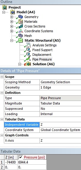
On the left is the Tabular Data approach, and on the right is the Function approach.
This pipe model has elements that are 1 foot long, so there are only 6,200 elements.
I don't recommend a shell model because a shell element doesn't want to have an extreme aspect ratio. If the aspect ratio is limited to 10, and if 6 elements are put around a 1/4 circle, the edge length of those elements are 0.048 inches, so the edge length in the pipe length direction would be 0.48 inches, which means there would be 154,000 elements along the length or 924,000 elements in the model. And that is just for a shell model which can't represent internal and external pressures independently.
-
July 13, 2019 at 4:35 pm
daveberutu
SubscriberThank you mr jj, I can modelize the 2 function pressure load with split the line body into 2 parts. And my final problem now for line body method is still a solver pivot warning. Here I attach the model. I've tried any possibilities with the boundary condition and it doesnt fix anything.
Your help will be much appreciated
-
July 13, 2019 at 4:40 pm
-
July 13, 2019 at 4:49 pm
-
July 13, 2019 at 5:05 pm
daveberutu
SubscriberThank you Mr peteroznewmann, the result is satisfying. I really appreciate your help from the beginning.
-
November 6, 2022 at 6:17 pm
Wilmar Augsuto
SubscriberHi Everyone
I'm also have similiar problem. Maybe some of you will succed from this solution /forum/forums/topic/solver-pivot-warning/ . But for mine, this brings me nowhere. I'm have tried all the solution given but still can't solve the problemThis Message Shows after I run a solver :
Solver pivot warnings or errors have been encountered during the solution. This is usually a result of an ill conditioned matrix possibly due to unreasonable material properties, an under constrained model, or contact related issues. Check results carefully.
Your help will be much appreciated
-
- The topic ‘A solver pivot warning or error has been detected’ is closed to new replies.


-
5084
-
1823
-
1387
-
1248
-
1021

© 2026 Copyright ANSYS, Inc. All rights reserved.


