TAGGED: mesh-generation, skewness, velocity-contours
-
-
January 23, 2022 at 1:25 pm
m.shafiee1374
SubscriberHi,
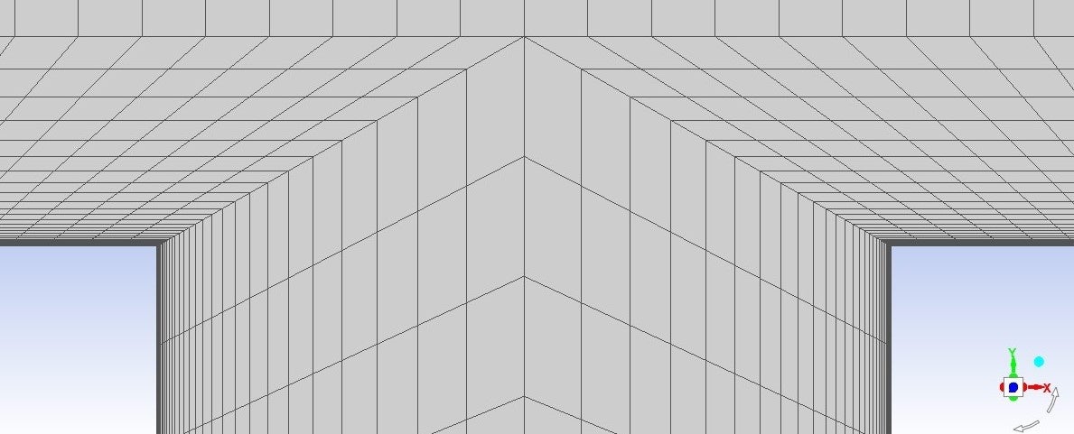
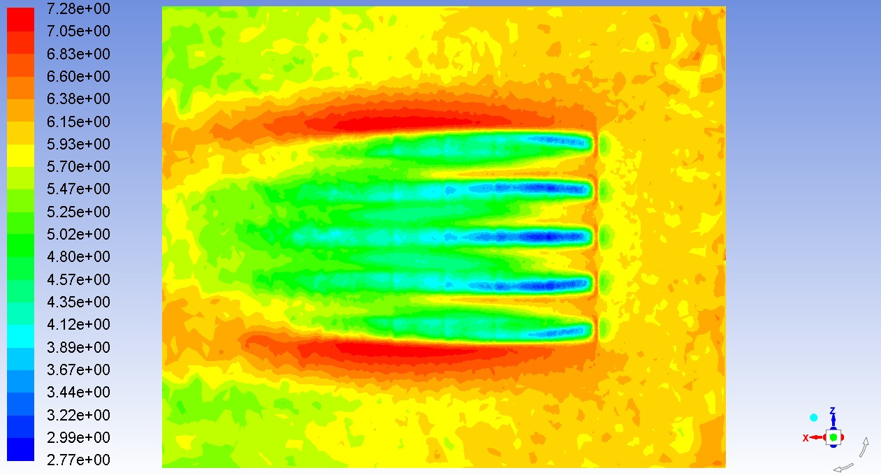
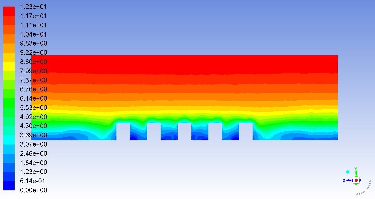
I ran a steady 3d simulation of a grid shown in the first picture using realizable k-e turbulence model, and my mesh skewness across all my domain is below 0.65 (which is acceptable according to fluent guidelines). However, I find some irregularities in the velocity contour at locations with highest skewness (second picture). Now I'm worried about another geometry with a bit higher max skewness(<0.75), and whether that will give me acceptable results or not.
Can this issue be solved by changing any of the simulation parameters? Or changing the mesh (which I'd rather not) is the only way to fix it?
Thanks :)
p.s. I'm using Ansys Workbench 17.0 for this project.
January 24, 2022 at 4:38 amKeyur Kanade
Ansys EmployeePlease check orthogonality. The min orthogonal quality should be above 0.1 to proceed to solver. If it is less than 0.1 then please improve the mesh.
First check the locations of the bad elements. Please see following video for the same.
https://www.youtube.com/watch?v=ZDADSSN8hOs
Once you have locations, please check if you can improve mesh using different mesh sizing. Please see following video.
https://www.youtube.com/watch?v=w4q6q8nKF3U
Please go through help manual for more details
Regards Keyur
How to access Ansys Online Help Document
Guidelines on the Student Community
January 24, 2022 at 11:17 amRob
Forum ModeratorReading this thread may also help /forum/discussion/32082/a-mesh-resolution-and-y-problem#latest
January 24, 2022 at 1:07 pmSubscriberHello I checked my mesh quality and my min ortho quality is 0.387 and max ortho skew is 0.613, so i assume there are no "bad quality elements" .
--------------
And regarding this thread which was also mine:
I managed to solve the divergence issue by reducing the under-relaxation factors of pressure, momentum and turbulence properties by 0.2 as was suggested by the Fluent guide.
Also there are no blocking here, because I'm using Gambit not ICEM. I've decomposed the domain into lots of smaller volumes to be able to generate a structured hex mesh.
However, I'm going to refine my mesh in this area to reduce the "jump" in aspect ratio and cell size. Hopefully this might work...
Thanks for your answers.
January 24, 2022 at 1:16 pmForum ModeratorOrtho quality and skew are only part of the problem. You also need to avoid large jumps in cell size and add sufficient mesh to resolve the gradients: in your case you have jumps in cell size in the same region as the relatively steep gradients.
Fixing this isn't as straightforward. GAMBIT is about 10-15 years from it's last update, and whilst it has several powerful features has been largely superceeded by the current geometry tools and Fluent Meshing. Using a poly or poly-hexcore mesh on the entire fluid region will reduce the jumps in cell size, and allow you to then use either adaption or controlled growth rates to get a better mesh around the pins/stubs.
February 5, 2022 at 10:21 amSubscriber
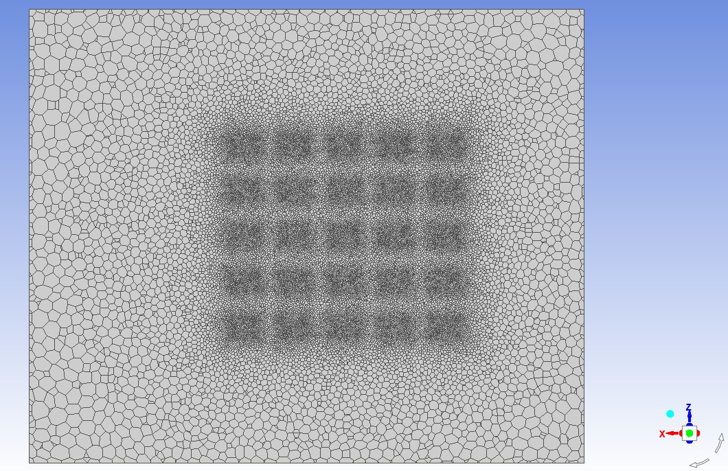
Hello Rob So I went ahead and generated a tetrahedral mesh using icem cfd, then imported it to fluent and converted the mesh to polyhedral as you suggested.
I've also smoothed the mesh to make sure its quality is within the acceptable range.
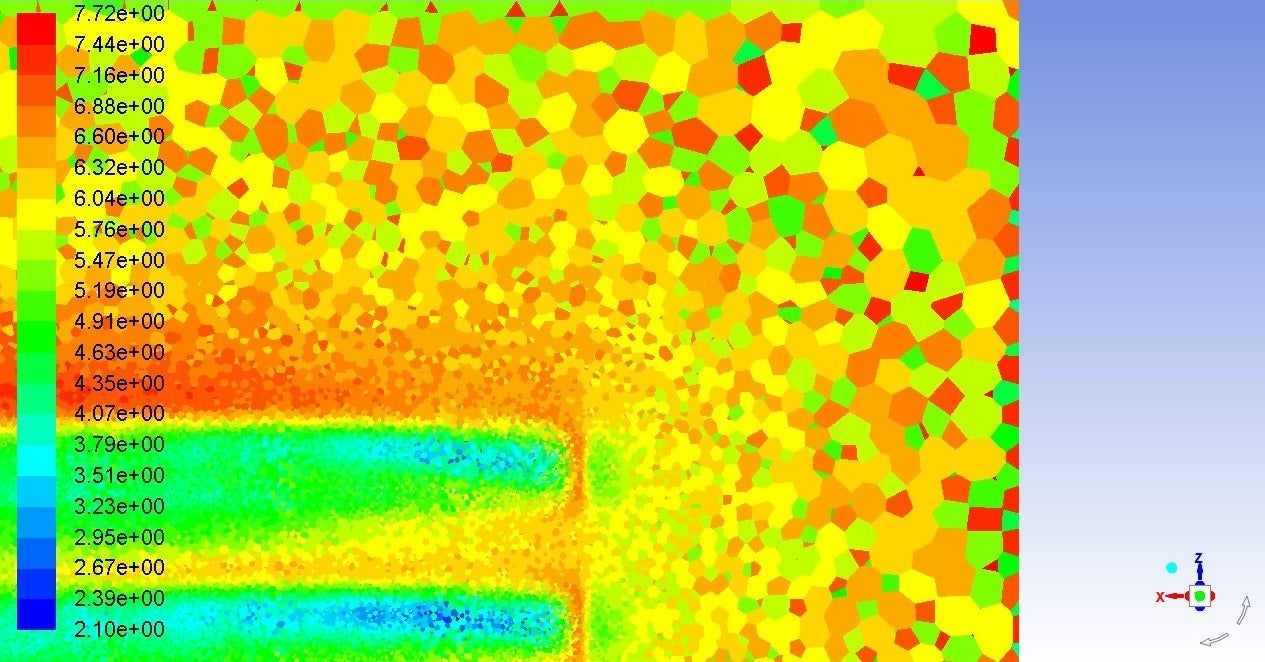
But now the velocity contour in the x-z plane looks like this:
 Since I'm completely new to icem/poly mesh, I expect there must be a way to smooth these results?? Or should i use even a finer grid?
February 7, 2022 at 4:58 pmForum ModeratorWhere is that plane relative to the obstructions?
February 7, 2022 at 6:47 pmSubscriberThose obstructions are 10 meters tall and this plane is 1 meter above them.
February 8, 2022 at 9:38 amForum ModeratorZoom in and replot with node values off.
February 8, 2022 at 11:41 amSubscriber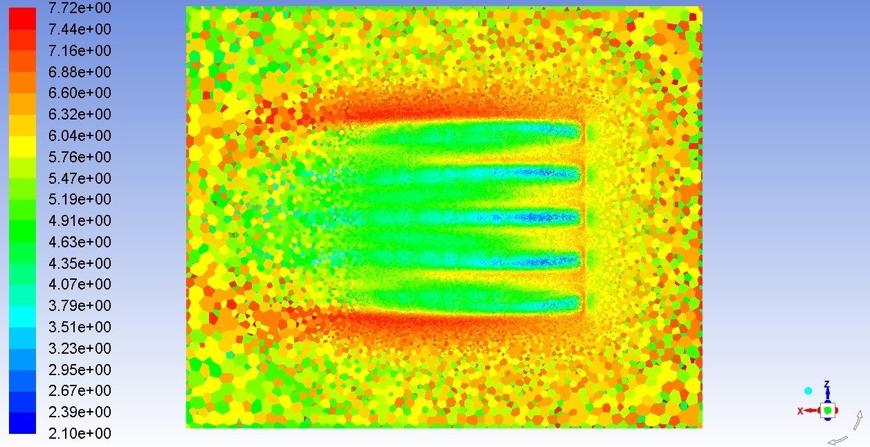
February 8, 2022 at 12:05 pmForum ModeratorThat's weird. How's the convergence? I've only seen that effect where there was only 1-2 cells between the plotted surface and a wall.
February 8, 2022 at 2:50 pmSubscriberConvergence is pretty good actually, better than the hex mesh, solution converged after around 400 iterations with residuals less than 0.001 and no fluctuations in them .
There's also much more than 2 cells between the contour plane and the wall boundaries.
I also didn't see this problem in the contours plotted on the x-y or y-z planes, which is super weird.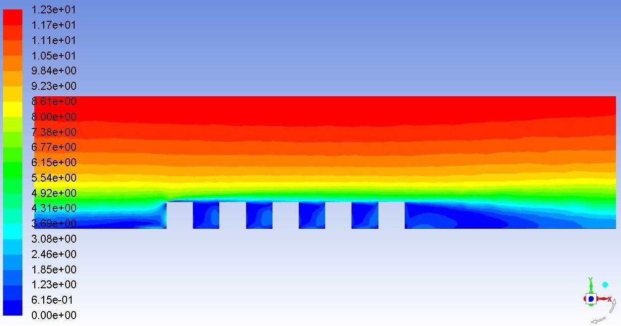
February 8, 2022 at 4:33 pmForum ModeratorBut you do have very disturbed contour boundaries in the vertical plane: look at the bounds of the green and yellow contours.
February 10, 2022 at 8:08 pmSubscriber
I figured what the problem was. Since im using a custom velocity profile at the inlet, my velocity gradient in the vertical direction around the location at which this contour is plotted, was higher than that my mesh could resolve. Which means I have to refine my grid near the bottom of the domain in the vertical direction, but I'm struggling to do so because fluent runs out of memory during tetra to poly conversion.
I'm open to suggestions, and once again thanks for your answers.
February 11, 2022 at 11:08 amForum ModeratorRead the geometry into Fluent Meshing and create the poly mesh directly. Memory overheads are significantly reduced and you don't then need to go anywhere near GAMBIT.
Viewing 14 reply threads- The topic ‘A mesh skewness problem’ is closed to new replies.
Innovation Space Trending discussions
- air flow in and out of computer case
- Varying Bond model parameters to mimic soil particle cohesion/stiction
- Eroded Mass due to Erosion of Soil Particles by Fluids
- I am doing a corona simulation. But particles are not spreading.
- Centrifugal Fan Analysis for Determination of Characteristic Curve
- Guidance needed for Conjugate Heat Transfer Analysis for a 3s3p Li-ion Battery
- Issue to compile a UDF in ANSYS Fluent
- JACOBI Convergence Issue in ANSYS AQWA
- affinity not set
- Resuming SAG Mill Simulation with New Particle Batch in Rocky
Top Contributors
-
peteroznewman
 4052
4052 -
scabo
 1482
1482 -
Dennis Chen
 1308
1308 -
javat33489
 1156
1156 -
Shyam Prasad V Atri
1021
Top Rated Tags
© 2025 Copyright ANSYS, Inc. All rights reserved.
Ansys does not support the usage of unauthorized Ansys software. Please visit www.ansys.com to obtain an official distribution.
-