-
-
March 18, 2021 at 11:36 am
Rameez_ul_Haq
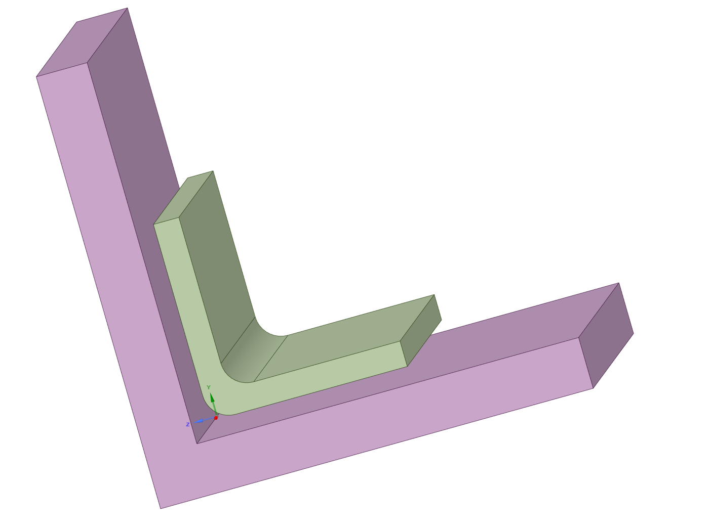
SubscriberPlease observe the BONDED contacts below:
March 18, 2021 at 11:54 ampeteroznewman
SubscriberArray
The sharp corner will not affect the stress at the bond interface as the elements get much smaller than the distance between the edge of the blend and the sharp corner, as long as the Pinball Radius keeps changing to smaller values as the elements get smaller to keep the bond from spidering out to the sharp corner.
If you expect the stress to rise at a crack tip, is that abnormal or unusual? The bonded angle clip has a blend which creates a crack tip with the flat face of the larger part. Crack tips are stress singularities on their own. High stress at a crack tip is normal and usual. There are methods to evaluate the cohesive failure of an adhesive at a crack tip, such as Cohesive Zone Models (CZM).
March 18, 2021 at 1:36 pmSubscriber.peteroznewman, regarding your second paragraph, what do you mean by 'bonded angle clip has a blend'? I mean I am just simply asking this because of the nature of the bonded contact, or any other contact, should I expect any any unusual stresses at the corners of the contact, where the contact is finishing? This includes the region I have already marked in red, and also the side edges where the contact is finishing (since it creates a sharp interior angle between the two bodies). Rather it be a surface to surface contact (not shown here) or solid face to solid face (as shown in the pictures).
Same can be thought as for shared topology, like if I connect two bodies like shown in the second picture using shared topology, so there would a sharp interior angle between them but they are two separate bodies. Should I expect a singularity there because of that geometric feature, or any other kind of abnormal stresses?
I dont know why did you include the crack tip analogy into this discussion. I mean they bodies here donot represent any kind of crack tips, just two simple bodies connected with each other, and I am trying to figure out what would ANSYS return me because of the mathematics behind it.
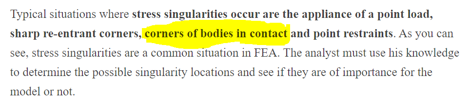
In an article (https://www.linkedin.com/pulse/stress-singularities-concentrations-mesh-fea-marcos-ac%C3%ADn-gonz%C3%A1lez), it is written that:
. Now, regarding the first paragraph you wrote, I conclude that my statement, "I mean the loads will only get transferred to/from the upper geometry which makes me think that the singularity in the bottom geometry should not at all effect the stress results within my upper geometry." is correct then?March 19, 2021 at 8:34 pmSubscriberArray, your thoughts on this would be very helpful.
March 19, 2021 at 9:08 pmSubscriber.Rameez_ul_Haq
The green part is the bonded angle clip with a blend. The edge you circled in red is the crack tip because the adhesive ends and the materials on each side continue. That is like a crack.
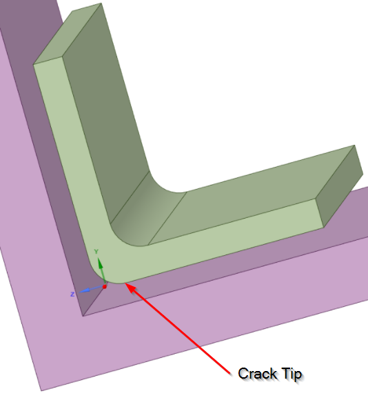 Crack tips have higher stress than edges where the adhesive and the material end together, like along the side, because the material extension past the end of the adhesive provides a lever arm to increase the force. The way to avoid this being a crack tip is for the adhesive to fill the gap between the two parts.
A more typical design would be the purple part is made of two plates that are joined by the green angle clip. What is the angle clip for if the purple part is already one piece?
In the example as shown, for both Bonded Contact and Shared Topology, there are stress singularities at all the interior corners made between the two parts, so basically everywhere.
.March 20, 2021 at 9:17 amSubscriberArray, "In the example as shown, for both Bonded Contact and Shared Topology, there are stress singularities at all the interior corners made between the two parts, so basically everywhere." So this singularity should be affecting the stresses around that geoemtric feature (sharp interior corner) within both the bodies, right? [Assume average accross bodies is turned 'OFF'].
March 20, 2021 at 2:13 pmSubscriberArray
If the singularity is created by two bodies joined by shared topology or bonded contact, elements along the singularity will be affected on both bodies.
Several elements away from the singularity, the stress will not be affected, as St. Veneant's principle applies.
December 19, 2021 at 8:29 pmSubscriber.peteroznewman, you said somewhere (maybe not on this thread) that a way to get rid of singularity would be implement a material non-linearity within my analysis. So what do you think, can the stresses near this geometric singularity still be trusted after applying the material non-linearity? I mean for a linear material analysis, we are aware that refining the mesh near this geometric singularity region wil lead to increase in stress at the singularity region and these cannot be trusted at all, but what about the stresses at the same geometric singularity region after applying the material non-linearity? Can the stresses in this singularity region now be trusted?
.December 19, 2021 at 9:40 pmSubscriber.Rameez_ul_Haq
You can't take something I said somewhere and apply it elsewhere, because what I said may not apply in a different context. I believe you are recalling the case where a ductile metallic part with a sharp interior corner was exceeding ultimate tensile stress using a linear elastic material model. In that case, adding plasticity to the material model was helpful to make a preliminary evaluation of the initial design.
This discussion is about stresses near angle clips bonded to panels. Your other discussion /forum/discussion/comment/141682#Comment_141682
has composite panels that have bonded contact. Are you asking about the singularity in that situation, which is similar to this thread?
.December 19, 2021 at 9:42 pmSubscriber.peteroznewman, yes. I am asking about singularity because this post is dedicated to singluarity. I didn't want to post this question in that thread because that was not the aim of that thread. This is just a general query, and has nothing to do with the other thread at all.
.December 20, 2021 at 2:27 pmSubscriber.Rameez_ul_Haq
The general approach to resolving a singularity at a geometric discontinuity is to build a detailed sub-model where the geometric discontinuity can be eliminated. For example, if adhesive is used to bond one plate to another in a single lap shear type of joint, in reality, there may be a fillet of adhesive at the step.
.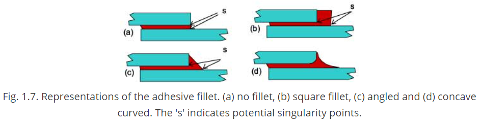 Read this report on how to analyze adhesively bonded joints. https://www.twi-global.com/technical-knowledge/published-papers/modelling-of-adhesively-bonded-joints-april-2001December 20, 2021 at 4:39 pmSubscriber.
peteroznewman, sir I completely understand your suggestion. But what I was asking is something different. Assume I am going for inputting material non-linearity in order to eliminate the stress singularity (because we know that is an option). Or just assume I want to input the material non-linearity. Now, at the same singularity region (which was shown singularity stresses when no material non-linearity was inputted), should I trust the stresses now after inputting material non-linearity? Or they will just not make the singularity stress increase exponentially with element refinement, but still they cannot be trusted? I hope you know understood my query.
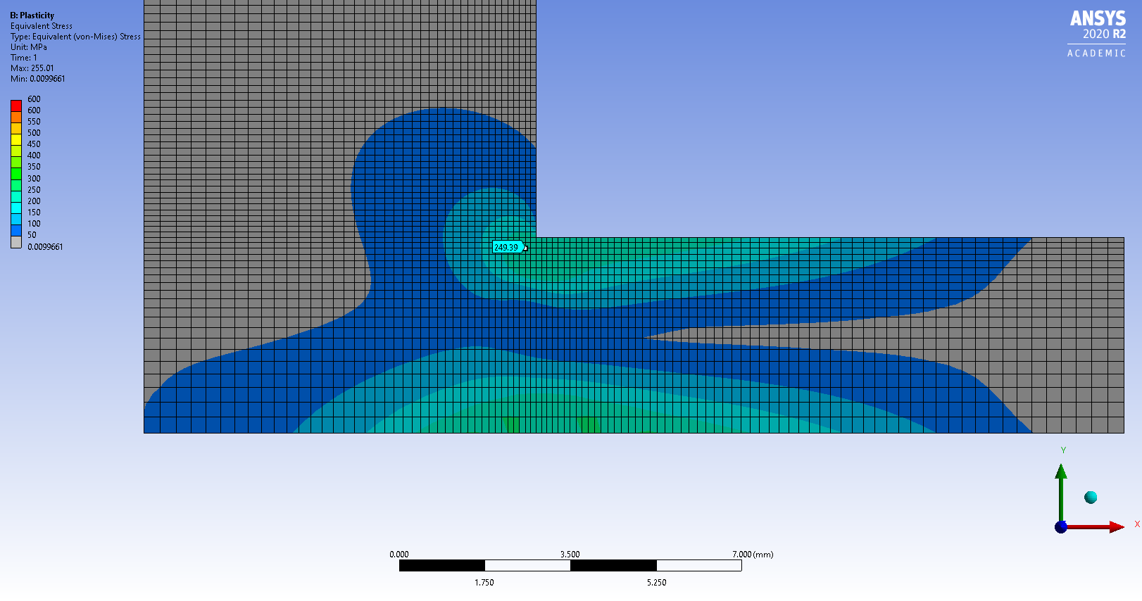
.December 20, 2021 at 8:55 pmSubscriber.Here is an example of a singularity with a linear elastic material and the same model with plasticity added with a yield strength of 250 MPa and a tangent modulus of 1e7 Pa.
In the Linear Elastic model, I show a node two elements away from the corner. The stress is 240 MPa, but the maximum stress in the model is 768 MPa.
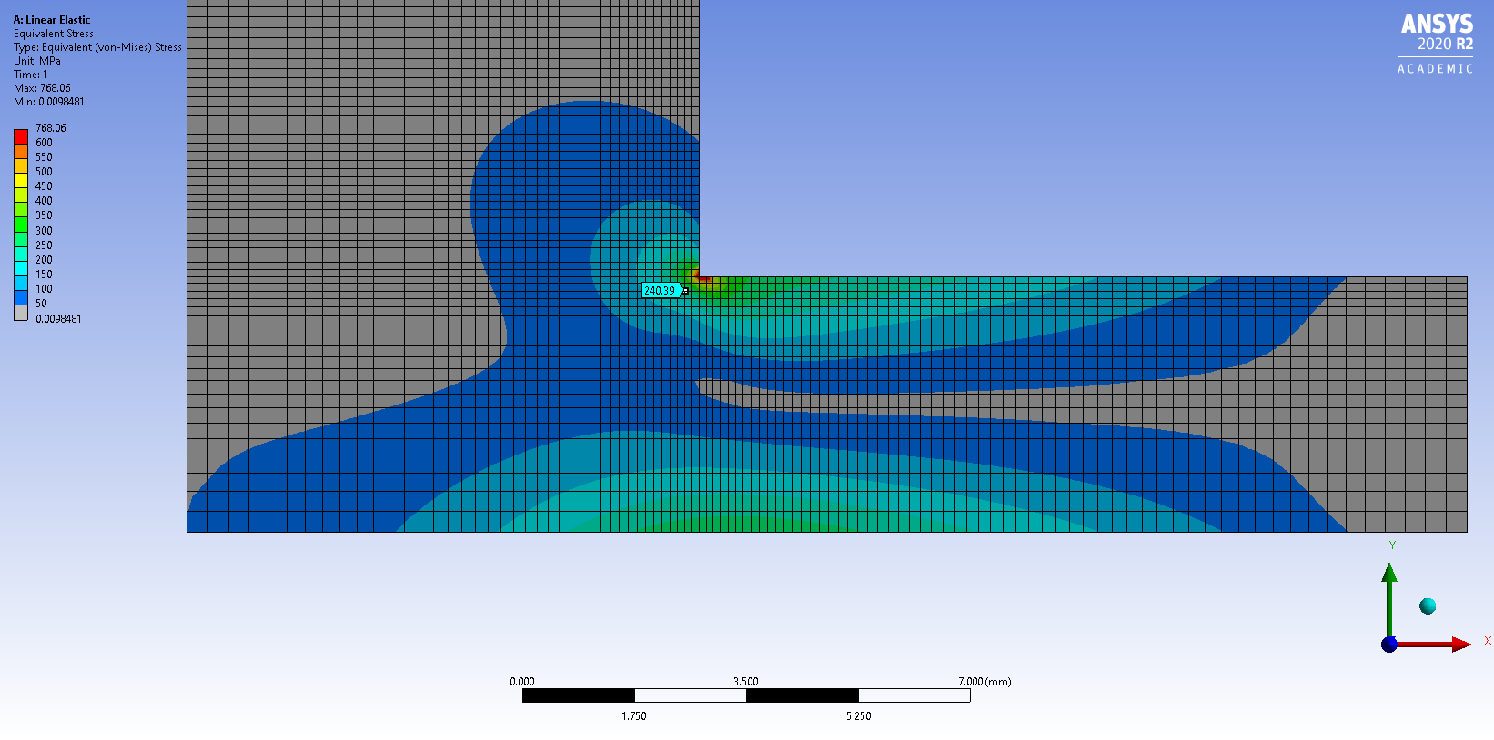 In the Plasticity model, the same node two elements away from the corner shows a stress of 249 MPa, which is less than 4% different, so below yield, you can trust the stress values on the part of the model below yield. However, the maximum stress in the plasticity model is 255 MPa, while the 768 MPa from the Linear Elastic model has a 200% error and moreover, is entirely dependent on element size.
. December 21, 2021 at 7:27 amSubscriber.
peteroznewman, I am assuming that still the max stress of 255MPa (above yield strength) in the plasticity model is occurring at the same region where you had 768 MPa at the corner (geometric singularity). So should I trust this stress of 255 MPa? Should I be anticipating this stress in reality, which is occurring at this geometric singularity in this FEA model? I know that in reality no geometric singularity is present since there will always be somewhat a curve inplace of a sharp corner. But just assume that the curve's radius is so small in reality, that it can be considered as a sharp corner.
.December 21, 2021 at 12:51 pmSubscriber.Rameez_ul_Haq
The corner stress has gone down because the material stretching with plastic strain has relieved the stress in the corner.
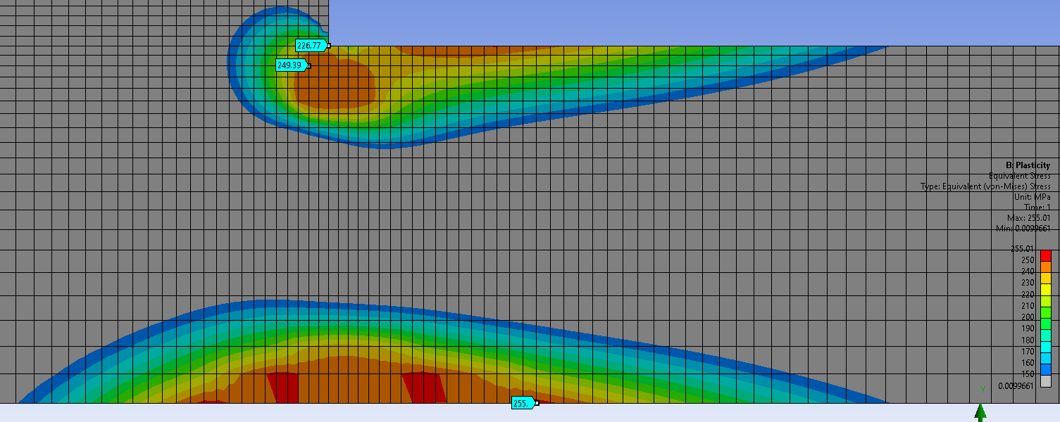 The level of trust in the 255 MPa depends on the level of trust you have in the nonlinear stress-strain curve that has been used in the model, and the proper attention to mesh refinement study. In the image above, the elements are too large in the vicinity of 255 for this to be a very precise value, however, if I was writing a report on this part, I would not be concerned with obtaining a precise value of stress on a part that has gone past the yield strength. I would be looking at the Equivalent Total Strain, shown below to be at 2% in the corner and compare that value with the material property, Elongation at Break.
.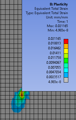 If the Elongation at Break was 1%, then a crack has appeared in this corner. If Elongation at Break was 6%, then I have a good margin of safety from a crack appearing.December 21, 2021 at 4:43 pmSubscriber.
peteroznewman, first of all thank you sir for providing with such clear and illustrative figures. I extremely appreciate your effort, thank you for this.
The mesh refinement study for a model which incudes material plasticity also make the stresses to diverge at the singularity? (as it does for the linear material model). Asking this just for general information, like what do you think about this?
And yes, comparing max eqv. total strain with the strain in my stress-strain curve should be the better option to check if the material has undergone only permanent plasticity, or has even experienced crack/breakage. Because a mesh refinement study might make the stresses at the singularity to diverge (even for my non-linear material model) but the strains won't. Which graph should I be using for comparison, True or Engineering?
.December 21, 2021 at 10:39 pmSubscriber.Rameez_ul_Haq
I only tried a mesh refinement study with plasticity one time and it did not go well. It's more useful for linear elastic materials where the stresses are expected to be less than yield.
The output from Ansys is True Stress and True Strain.
.December 22, 2021 at 8:52 amSubscriber.peteroznewman, thank you. But I was correct, right? That displacement results and strain results will not feel the effect of singularity i.e. they will never diverge? Its only the stress that diverge upon mesh refinement in a singularity region. Right? I just want to re-confirm this statement.
.December 22, 2021 at 2:33 pmSubscriber.Rameez_ul_Haq
Stress and strain are both computed from the same source, the element integration points, so both would diverge at a singularity.
Displacement is computed from the global stiffness matrix, so that should not diverge during mesh refinement at a singularity.
.December 23, 2021 at 5:01 pmSubscriber.peteroznewman, ohh okay. So strains would also show divergence at singularity with mesh refinement.
It appears from your comments that using material non-linearity in conjuction with singularity study is not the best of the options. I haven't tried singularity study (like mesh refinement and then observing the stresses/strains at that singularity region) along with material non-linearity, but I think I should because it is a very important issue in my sight. The reason I am saying this is because, think you have a singularity somewhere in the model (similar to the corner singularity you have already shown in your illustrations) and I am also using material non-linearity at the same time, so I think that the stresses/strains still cannot be dependable because thats a geometric defect (sharp corner) which should always exist there no matter analysis is material linear or non-linear. This means that I might be getting strains at that location which I would not be seeing in reality. And if I just observe a strain of 2% (where the elongation at break is 1%), then I might declaring that a crack will occur there but thats actually a singularity, and there might be no crack at all in the reality at that region.
What would you say on this? I would say that modifying the geometry to have fillets, or getting rid of singularity as a whole is the best option to give a verdict if a crack will originate there or not, instead of just declaring that a singularity by mesh refinement.
.December 24, 2021 at 12:08 amSubscriber.Rameez_ul_Haq
I talked about this point in the other discussion /forum/discussion/34604/is-this-a-singularity-or-an-actual-stress-concentration where I elaborated on the example from this discussion.
In that other discussion, I showed that there can be multiple singularities in the model. One of them has higher stress than that other. The singularity that shows stress higher than yield is treated with a fillet, while the singularity that has stress less than yield is ignored. That demonstrates a reasonable approach, to put effort in where it is most important.
.Viewing 20 reply threads- The topic ‘A couple of queries about contact and stresses near it.’ is closed to new replies.
Innovation Space Trending discussions
- The legend values are not changing.
- LPBF Simulation of dissimilar materials in ANSYS mechanical (Thermal Transient)
- Convergence error in modal analysis
- APDL, memory, solid
- How to model a bimodular material in Mechanical
- Meaning of the error
- Simulate a fan on the end of shaft
- Real Life Example of a non-symmetric eigenvalue problem
- Nonlinear load cases combinations
- How can the results of Pressures and Motions for all elements be obtained?
Top Contributors
-
peteroznewman
 4062
4062 -
scabo
 1487
1487 -
Dennis Chen
 1308
1308 -
javat33489
 1156
1156 -
Shyam Prasad V Atri
1021
Top Rated Tags
© 2025 Copyright ANSYS, Inc. All rights reserved.
Ansys does not support the usage of unauthorized Ansys software. Please visit www.ansys.com to obtain an official distribution.
-
General Mechanical
Topics related to Mechanical Enterprise, Motion, Additive Print and more.
A couple of queries about contact and stresses near it.


Ansys Assistant

Welcome to Ansys Assistant!
An AI-based virtual assistant for active Ansys Academic Customers. Please login using your university issued email address.

Hey there, you are quite inquisitive! You have hit your hourly question limit. Please retry after '10' minutes. For questions, please reach out to ansyslearn@ansys.com.
RETRY