TAGGED: angle
-
-
May 9, 2023 at 6:04 pm
xiao
SubscriberHi Community,
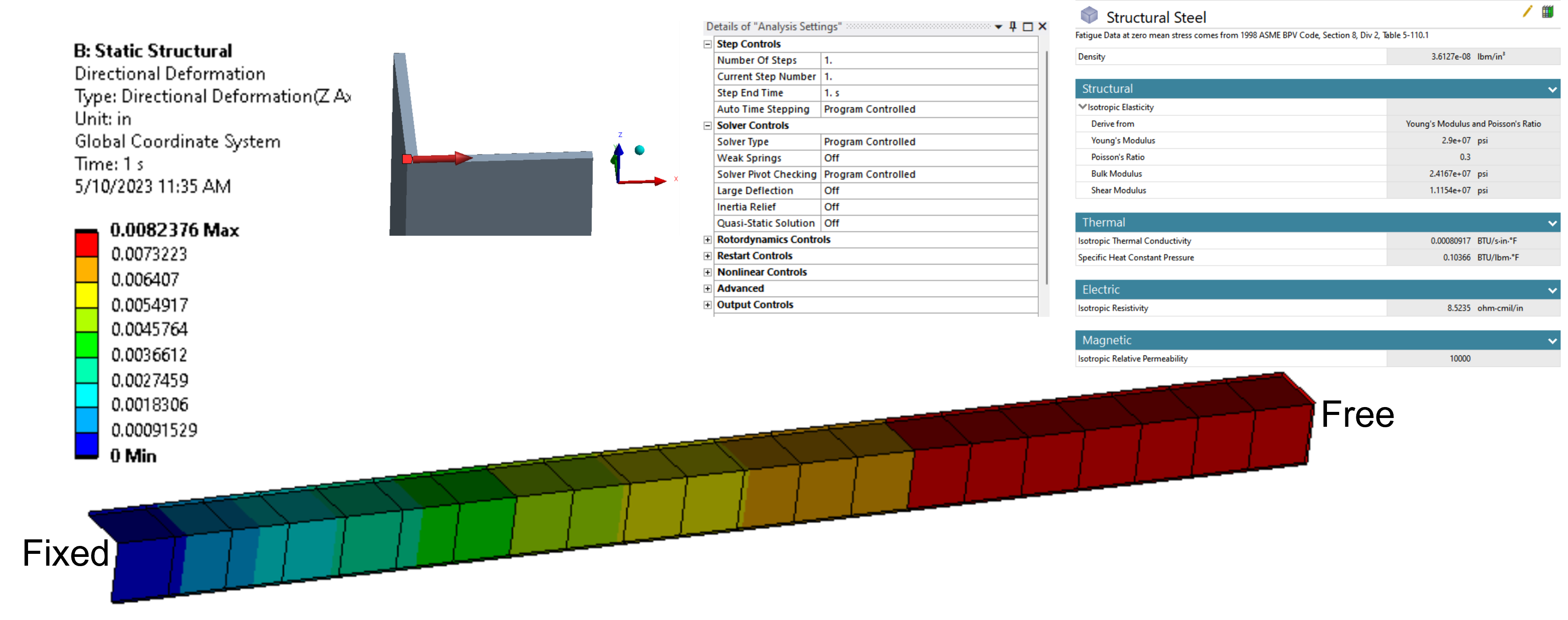
I modeled a simple cantilever beam element using beam188.
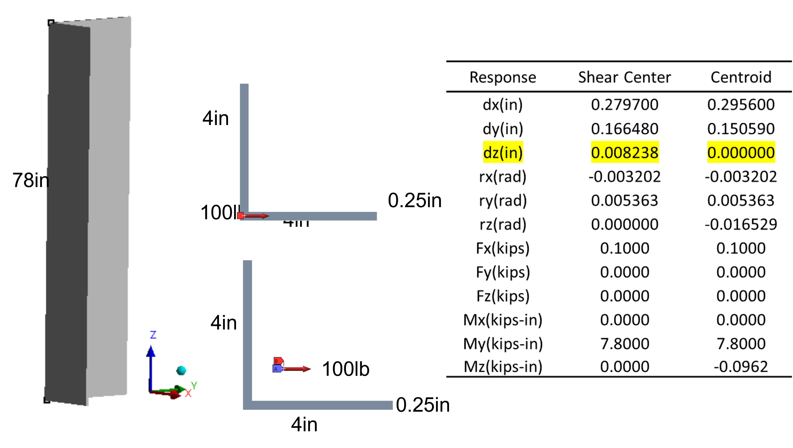
I want to compare the results of applying the force at 1) the shear center; 2) the centroid.
This is how I do it (maybe wrong):
1) When applying the force at the shear center, I offset the element in the shear center and apply 100lb x-direction shear force;
2) When applying the force at the centroid, I offset the element in the centroid and apply 100lb x-direction shear force.
What I expected is that except for the torsional displacement, the other responses should be the same.
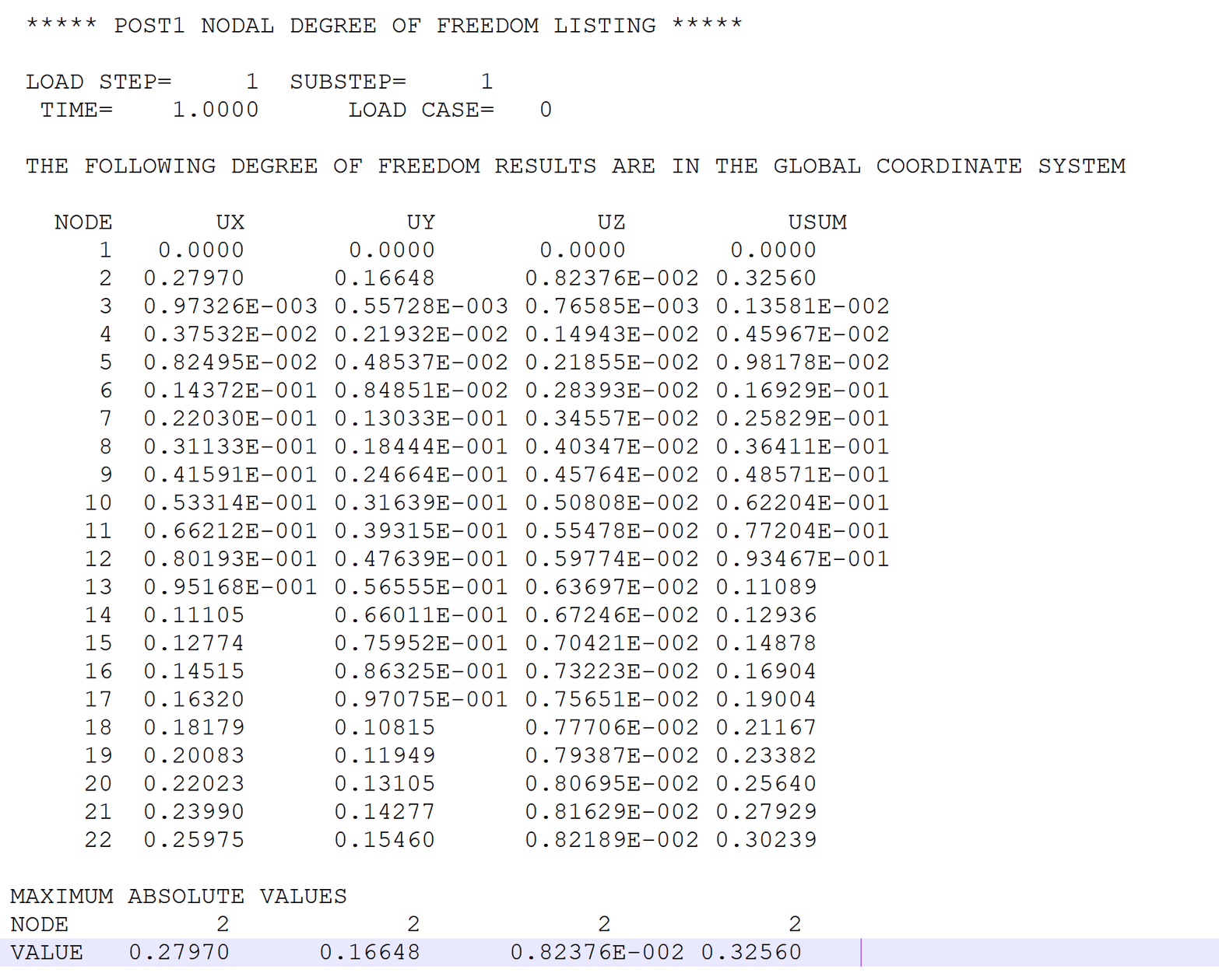
However, the results show that there is an axial deformation when applying the force at the shear center. Other translational displacements are close but not the same. I cannot interpret why there is an axial deformation.
Can anyone help me?
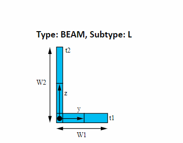
All the difficulties come from an unsymmetric cross-section!
Attached is the summary of the results.
Xiao
-
May 10, 2023 at 2:22 pm
dlooman
Ansys EmployeeIf large deflection is turned on there can be a small z displacement at the end of a cantilever beam. Also, PowerGraphics can produce a uz value due to the rotation of the cross-section. How are you retrieving the displacement?
-
May 10, 2023 at 3:13 pm
xiao
SubscriberHi Dave,
I turned the large deflection off because I want everything be to linear so that it is easier to interpret the results.
I used the probe to get the displacement and rotations. The chart is just for summarization only.
Â
Thanks,
Xiao
-
-
May 10, 2023 at 3:30 pm
dlooman
Ansys EmployeeIf you display a 3D image of the deformed beam do you see a location where there is non-zero uz displacement at the end? Â
-
May 10, 2023 at 3:42 pm
-
-
May 10, 2023 at 3:48 pm
dlooman
Ansys EmployeeIs uz perhaps equal to rotation times the depth of the section? That would be a good "sanity check."Â
-
May 10, 2023 at 3:54 pm
xiao
SubscriberHi Dave,
The cross-section is double in length with dimensions to be 4x4x0.25in. Because I applied the shear force in the shear center, there is no torsion.
Xiao
-
-
May 10, 2023 at 5:22 pm
dlooman
Ansys EmployeeWhat's the rotation at the end of the beam due to bending?
-
May 10, 2023 at 5:37 pm
xiao
SubscriberHi Dave,
\theta_x = -3.2016e-003 ; \theta_y = 5.3627e-003.
Â
Xiao
-
May 10, 2023 at 5:39 pm
dlooman
Ansys EmployeeAre those values in radians or degrees? Â
-
May 10, 2023 at 5:56 pm
xiao
SubscriberHi Dave,
They are all in radians.
Attached is the archive file (I don't know whether you are allowed to open it, but it is here).
https://www.dropbox.com/s/5encqidxav4pru7/single%20column.wbpz?dl=0
Â
Xiao
-
May 10, 2023 at 6:23 pm
dlooman
Ansys EmployeeI needed to sign in. If these values are in radians then the rotation of the end of the beam would easily produce the axial displacement you are seeing. For example, if we say the distance from the centroid to the extreme fiber is 2 inches then 2*3.2e-3 = 0.006 and 2*5.3e-3 = 0.010
-
May 10, 2023 at 6:29 pm
xiao
SubscriberHi Dave,
The distance from the centroid to the extreme fiber is 1.56. From the calculation, 1.56*3.2e-3 = 0.005 and 1.56*5.3e-3 = 0.00826. The combined displacement is 0.0096. 1.56*5.3e-3 = 0.00826 value is close to the reported axial displacement. The combined one is not.
What you suggested is that the ANSYS probe command export the centroid displacement?
Â
Xiao
-
-
May 10, 2023 at 6:37 pm
dlooman
Ansys EmployeeSounds possible. You could check the centroid displacements in APDL POST1 with the commands:
set,last
prnsol,uÂ
Â
-
May 10, 2023 at 6:56 pm
xiao
SubscriberHi Dave,
I use the following commands to get the displacement.
set,last
prnsol,u
*cfopen,'axial-disp','txt'
*vwrite,u
(F20.12)
*cfclosThe result is 0.0
Xiao
-
-
May 10, 2023 at 7:07 pm
dlooman
Ansys EmployeeThat wouldn't work. *vwrite arguments are parameters. u is not a parameter.  Try this:
set,last
/out,axial-disp,txt
prnsol,uÂ
-
May 10, 2023 at 8:57 pm
-
-
May 10, 2023 at 9:07 pm
dlooman
Ansys Employee-
May 10, 2023 at 9:13 pm
xiao
SubscriberFrom the image, the node is at the shear center. Do you mean in ANSYS, we apply the load at the shear center?
For the case where the shear force is applied at the centroid, the axial displacement at the centroid will be zero, and the probe or displacement u will convert to the shear center?
Â
Â
Xiao
-
-
- The topic ‘3D cantilever beam apply shear in shear center and centroid’ is closed to new replies.
-
3597
-
1283
-
1117
-
1068
-
983
© 2025 Copyright ANSYS, Inc. All rights reserved.