-
-
October 19, 2023 at 4:34 am
Vinay Kumar Vemulapati
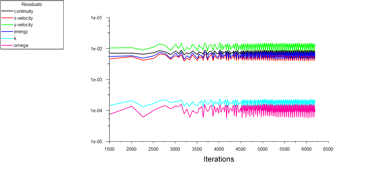
Subscriber"Artificial walls on 18 faces (1.4% area) of pressure-outlet 6 to prevent fluid from flowing into the boundary" while performing 2D analysis of Non reacting flow (i.e. no combustion). Also oscillation of Residuals.
Net Mass flow rate is nearly 0.
Mesh: 95,000 cells with inflation near walls
Model: SST k-ω
Boundary condtions
Inlet: Pressure farfield - Mach 2.0
Outlet: Pressure Outlet - (-1000 Pa), prevent reverse flow, Average Pressure specification
Solver: enabled high speed numerics
Initialization: Standard initialization and fmg initialization

-
October 19, 2023 at 2:04 pm
Federico
Ansys EmployeeHello Vinay,
You get the written warning because you have set the condition to Prevent Reverse flow. As a result, Fluent is creating "artificial walls" on 1.4% of your outlet surface area to prevent any flow from entering back through the outlet. This can happen if your outlet pressure is lower than the outlet BC over the course of simulation.
Regarding your residualts, can you show some contour plots of Velocity or Mach number?
-
October 19, 2023 at 3:16 pm
Vinay Kumar Vemulapati
Subscriber- Should outlet conditon need to be lower than -1000 Pa?
- Is it required to change flux type from Roe-FDS to AUSM. Most researchers used AUSM.
-
-
October 19, 2023 at 3:06 pm
-
October 19, 2023 at 6:59 pm
Federico
Ansys EmployeeYes, I would encourage you to use AUSM, which provides good shock resolution.
I cannot speak of the inlet/outlet conditions here, as this will be problem dependent.
-
October 20, 2023 at 2:44 am
-
-
October 20, 2023 at 1:39 pm
Federico
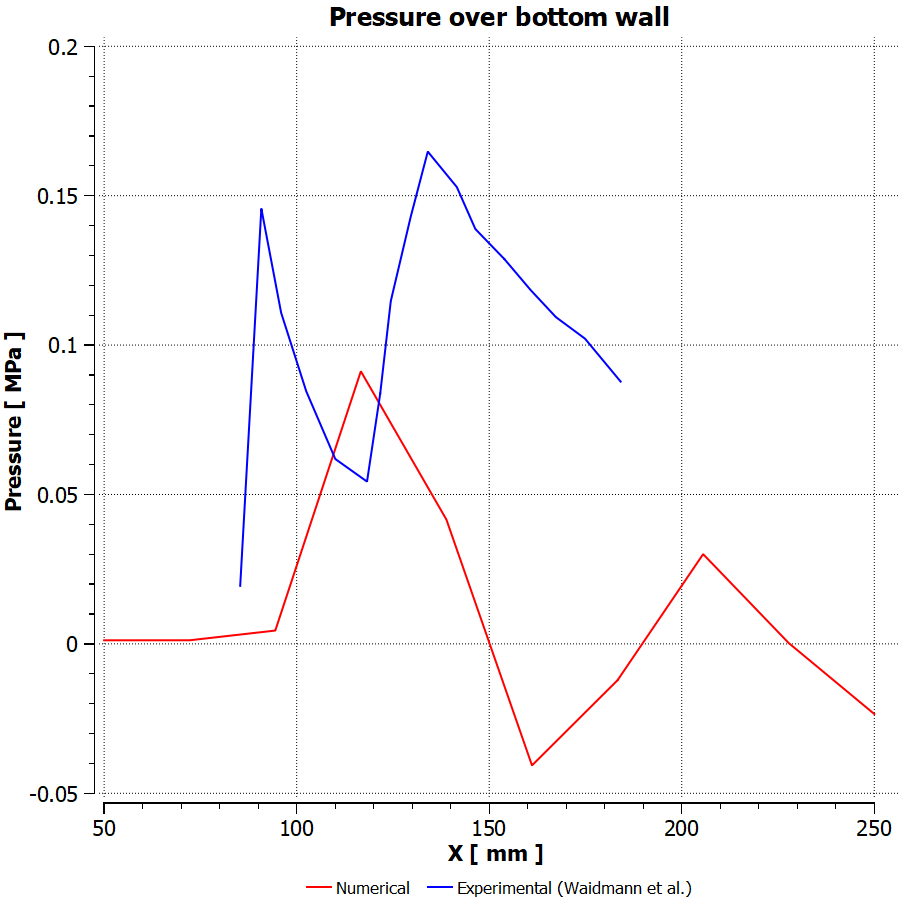
Ansys EmployeeThe static pressure in Fluent is a Gauge pressure, so it is relative to the Operating pressure that you have set. The default value for Operating pressure is 1atm, so the absolute pressure along the wall would be Static pressure + 1atm. Or you can plot Absolute pressure directly.
These pressure plots tell me that the mach number is higher in your simulation than the experiment. Why are you using -1000Pa at the outlet?
-
October 20, 2023 at 4:35 pm
Vinay Kumar Vemulapati
SubscriberSame outlet condition is used in ansys fluent ABP "Application Best Practices High-Speed Combustion Modeling with DLR SCRAMjet for For Ansys Fluent 2022R1".
-
October 20, 2023 at 6:09 pm
Federico
Ansys EmployeeAre those conditions the same in the experiment that you are comparing this with?
-
October 21, 2023 at 2:03 am
Vinay Kumar Vemulapati
SubscriberYes, but in numerical analysis they mentioned "Neumann boundary condition is used to define the outflow wall of the domain".
Boundary Conditions
Variable
Air
H2
Ma
2.0
1.0
U (m/s)
730
1200
T (K)
340
250
P (Pa)
100,000
100,000
⍴ (kg/m3)
1.002
0.097
Y(O2)
0.232
0
Y(N2)
0.736
0
Y(H2O)
0.032
0
Y(H2)
0
1
-
-
-
October 23, 2023 at 12:50 pm
Federico
Ansys EmployeeWhat are you showing me with this table?
-
October 25, 2023 at 3:47 am
Vinay Kumar Vemulapati
SubscriberInlet conditions of experiment.
-
October 25, 2023 at 12:11 pm
Federico
Ansys EmployeeAre you using the same for your simulation? What is your gauge pressure/Temperature at the inlet? What are your operating conditions?
-
-
October 25, 2023 at 4:46 pm
Vinay Kumar Vemulapati
SubscriberYes,
Guage Pressure = 0 Pa
Temperature at inlet = 340 K
Operating condition, Operating pressure=101325 Pa
-
- The topic ‘2D Analysis of DLR Scramjet Combustion’ is closed to new replies.


-
4613
-
1530
-
1386
-
1209
-
1021

© 2025 Copyright ANSYS, Inc. All rights reserved.


