-
-
October 16, 2024 at 1:51 pm
ashishkumar.gupta
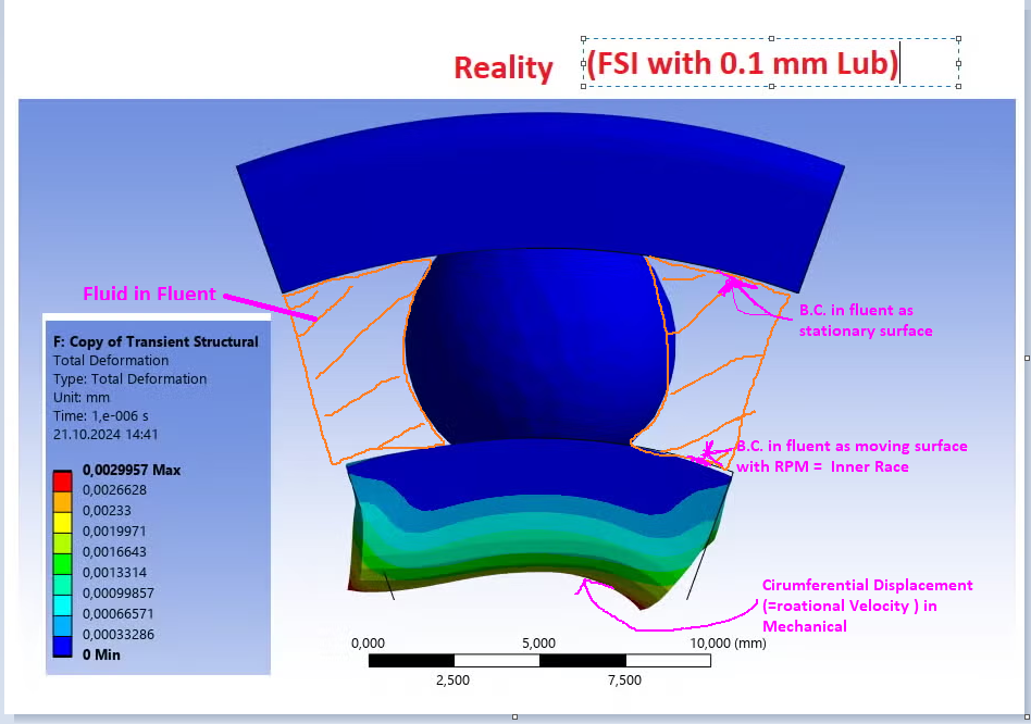
SubscriberThis is how it is modeled for 2- way FSI. I guess this is the right approach as due to the Forces from Oil it will cause some Displacement/movement of Races/Ball and Vice-versa.
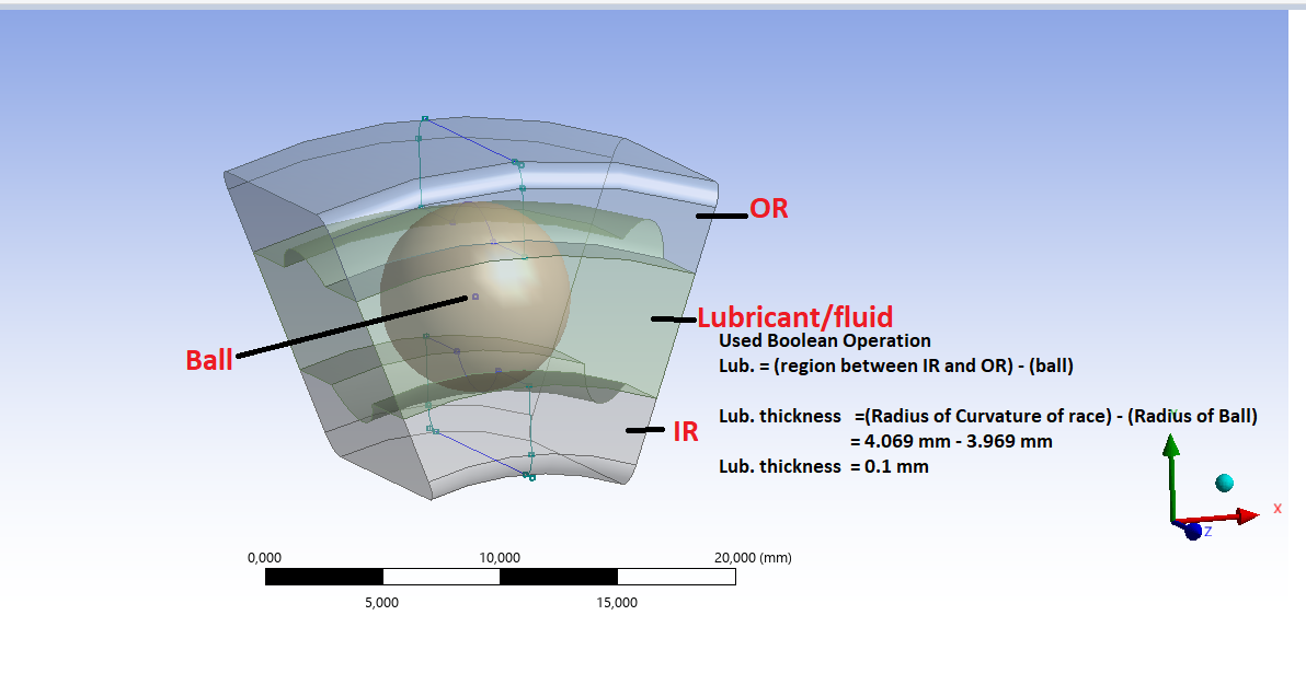
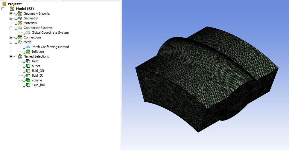
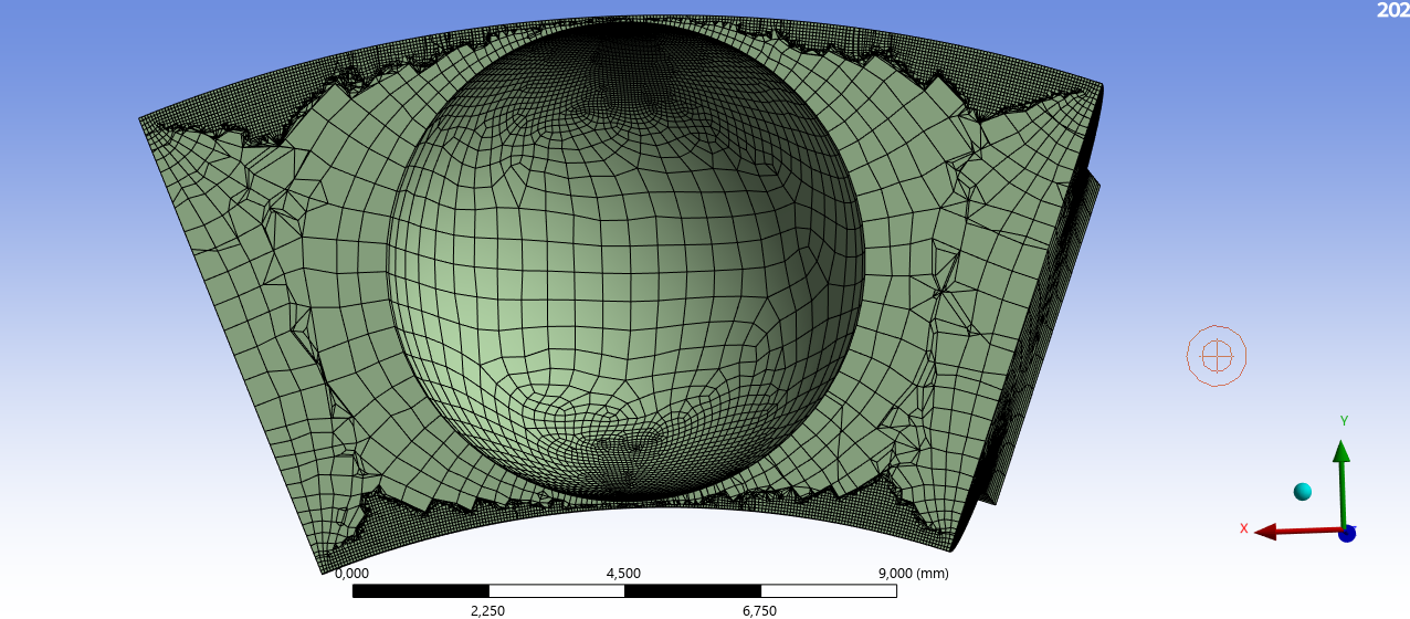
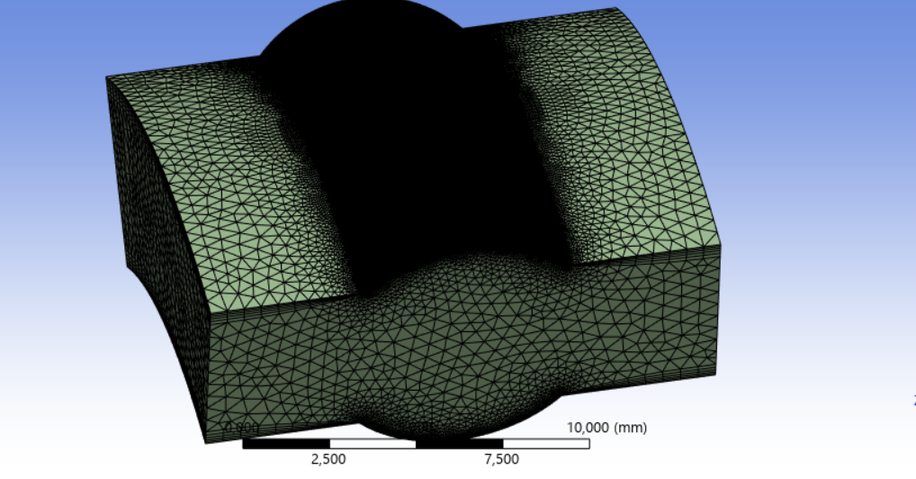
I have prepared a model with a ball, IR and OR.
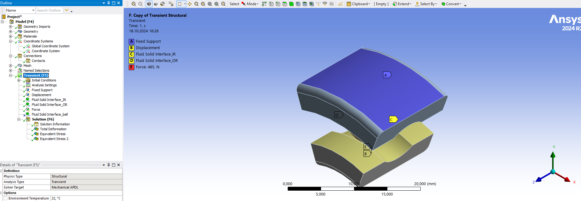
IR rotates (by giving circumferential Disp.) and radial force also applied bcoz of shaft and OR is fixed --- Transient
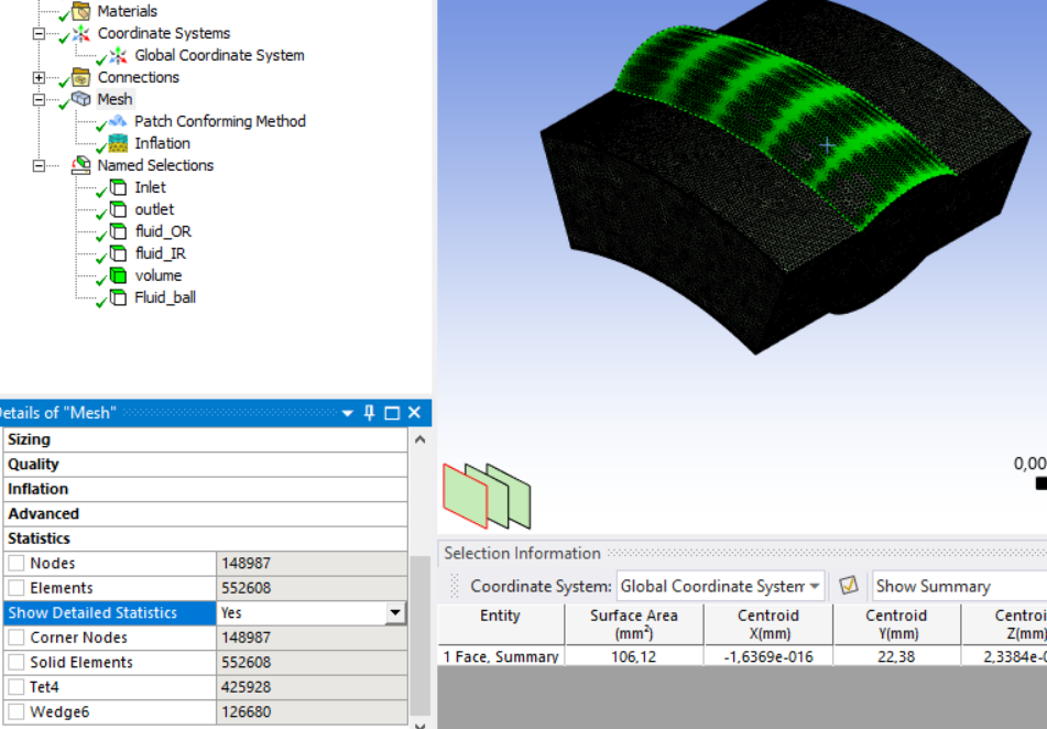
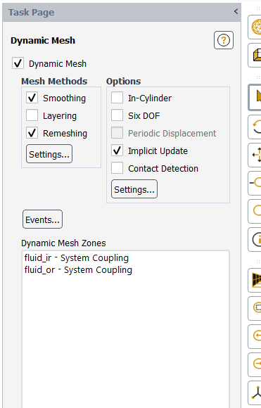
Lub. inlet on left side and outlet on another. Isothermal, incompressible fluid and SST k-w model used with Dynamic Meshing.
But the model does not run as there is no direct contact between ball and races.
any leads will be highly apprecitated to simplify the model. Thanks!
-
October 17, 2024 at 6:58 am
-
October 18, 2024 at 2:23 pm
Rahul
Ansys EmployeeIs it throwing any error?
-
October 18, 2024 at 2:33 pm
-
October 18, 2024 at 2:48 pm
Rahul
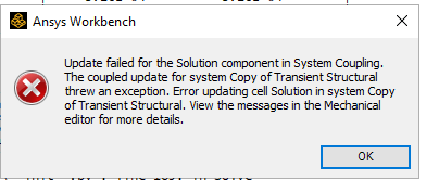
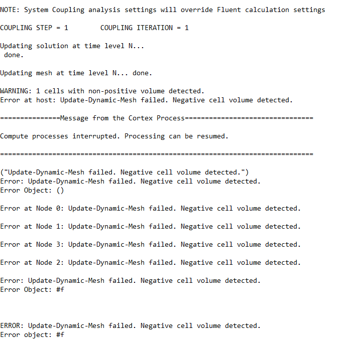
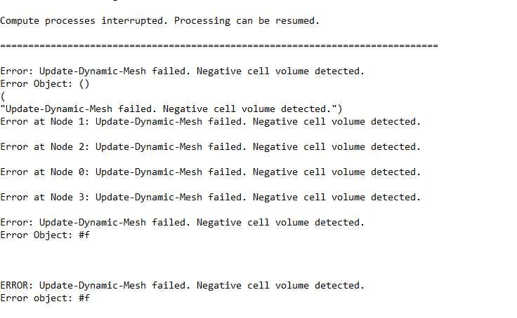
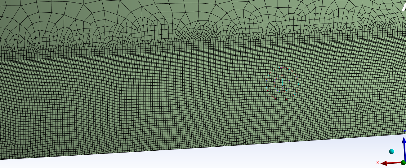
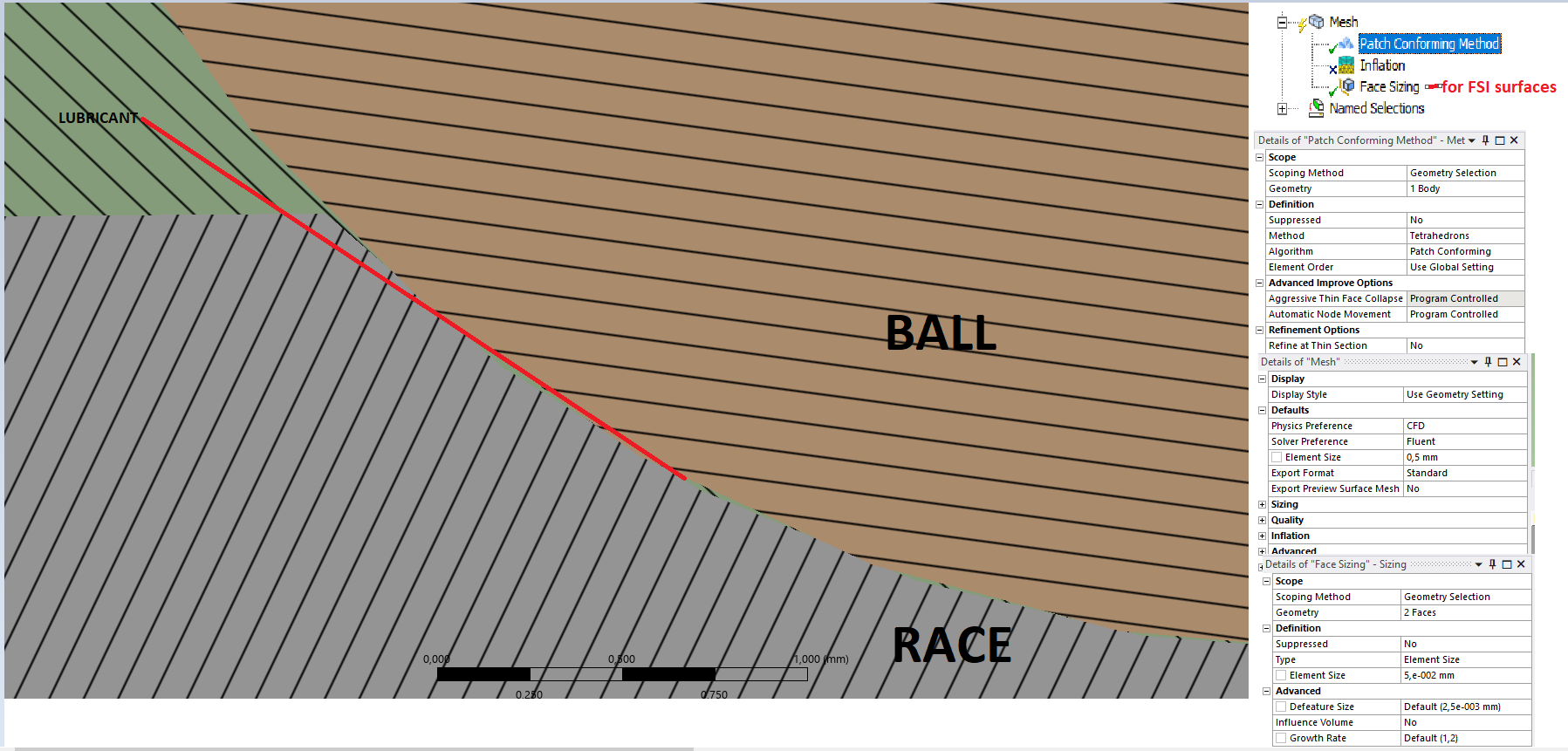
Ansys EmployeeNegative cell volume detected in Fluent. You can open the Fluent results and check the exact location of failure. I guess it is in the lubricant thickness region between the ball and the race. Have a sufficient number of cells of good quality in that region.
You can refer 'Mesh Folds within the First Coupling Steps' in the user guide: 42.6. FSI Setup Recommendations for Fluent-Mechanical Couplings (ansys.com)
-
October 18, 2024 at 3:11 pm
-
October 18, 2024 at 3:14 pm
Rahul
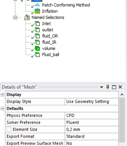
Ansys EmployeeHow many cells do you have in that thin region and what are the dynamic mesh settings? Are you using remeshing?
-
October 18, 2024 at 7:02 pm
-
October 19, 2024 at 5:07 am
Rahul
Ansys Employee- After failure, check the location of the mesh fold in Fluent and improve the mesh at that location using local sizing. Also, check the suggestions from 'Mesh Folds within the First Coupling Steps' in the user guide: 42.6. FSI Setup Recommendations for Fluent-Mechanical Couplings (ansys.com).
- Try applying the gradual load with ramping of data transfers to avoid the mesh failure at the start of the solution.
- Set lubricant zone to 'Deforming' in Dynamic mesh zones settings. You can refer to tutorial Reed Valve FSI Co-Simulation with Partial Setup Export from Workbench (Fluent-Mechanical) to understand the Two-way coupling setup.
-
October 19, 2024 at 12:15 pm
ashishkumar.gupta
SubscriberOkay I will try this now and revert back to you.
But you sure it is not because of Rigid body motion in Mech. but due to Coarse Meshing in Fluid? Because if we do fine meshing it is really time consuming, sometime taking 2-3 days and that is the reason for going for decent mesh over finer mesh.
-
October 21, 2024 at 6:58 am
Rahul
Ansys EmployeeYou can create a plane through the point of contact and investigate the mesh in that thin region.
To avoid negative volume, try defining the contact offset in Mechanical between those surfaces. You can find more information about it in Geometric Modification.
Negative volume generation issue could be due to several reasons:
1. First, check your mesh and ensure its quality is good. If not, please consider improving the mesh in the region where mesh motion is expected.
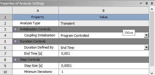
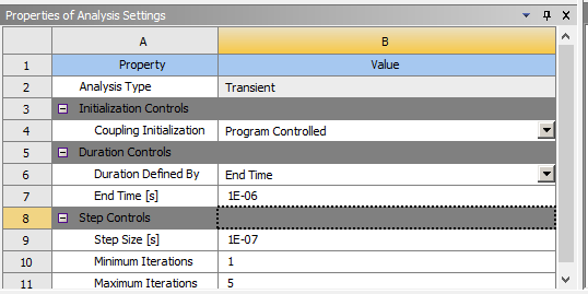
2. Consider reducing the time step. (change time in system coupling).
3. Check if unreasonable forces were received by Fluent leading to negative mesh in Fluent (Check BC in both participants and use data transfer ramping)
-
October 21, 2024 at 7:29 am
-
October 22, 2024 at 6:28 am
ashishkumar.gupta
SubscriberHi Rahul, could you please look into the updates and help me out. Thank you!
-
-
-
October 20, 2024 at 2:04 pm
-
October 21, 2024 at 12:49 pm
-
October 22, 2024 at 7:20 am
Rahul
Ansys EmployeeHello,
Check your boundary conditions here to see if the forces/displacement applied to the correct boundary.-
October 22, 2024 at 7:46 am
ashishkumar.gupta
SubscriberHey, Yes in the Transient Structural it is applied Correctly.
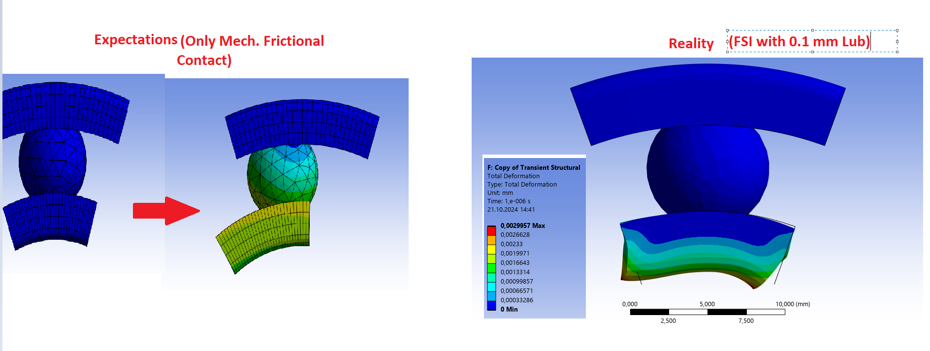
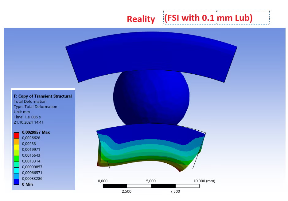
If I do not use FSI and keep frictional contacts in Transient Structural, The model works perfectly fine as shown in the LEFT image above.
If I use FSI with same setup but COULD NOT provide contacts in Transient Structural (as there is 0.1 mm Lubricant ), The model behaves as shown in the RIGHT image above.
-
October 23, 2024 at 6:32 am
ashishkumar.gupta
SubscriberHi, any update? Thank you!!
-
-
October 23, 2024 at 7:15 am
Rahul
Ansys EmployeeCheck if the forces from fluent are transferred correctly. Have you tried running a Fluent alone case? Is it working well?
Also, share the contact settings and BCs used in Mechanical participant.
-
October 23, 2024 at 8:09 am
ashishkumar.gupta
SubscriberHow do we check the forces from Fluent are transferred correctly or not?
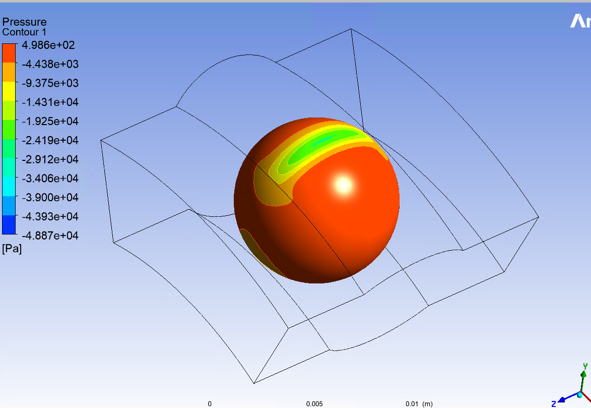
I simulated Fluent alone..It ran .. Since it is just the flow of fluid, I do not think it will be any problem.
The attached image below is of fluid pressure around the ball.
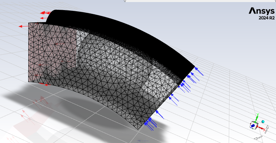
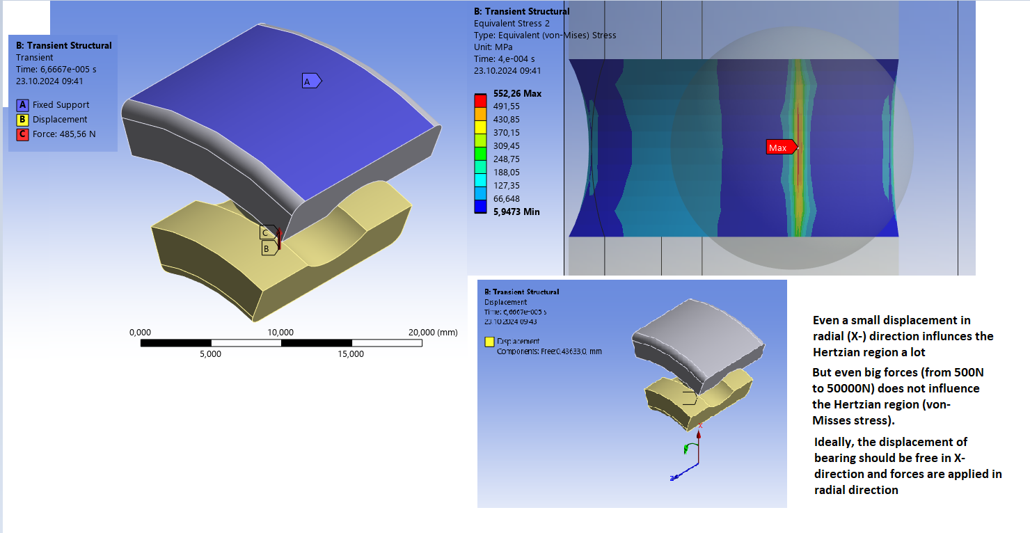
Below is the Mech. alone setup with frictional contact:
-
October 23, 2024 at 8:22 am
Rahul
Ansys EmployeeBy run fluent alone, I mean run Fluent alone with a representative load on the FSI boundary to see the mesh deformation and assess if it is solving correctly.
-
October 23, 2024 at 8:25 am
ashishkumar.gupta
SubscriberBut how do I calculate that load or pressure? Like the forces are transferred from races to Lubricant to ball...
-
October 23, 2024 at 9:30 am
ashishkumar.gupta
SubscriberCan u tell me how can I assess if the forces are being transferred fromn Fluent to Mech properly?
-
-
-
October 23, 2024 at 8:24 am
Rahul
Ansys EmployeeHave you removed this contact definition in the FSI case?
-
October 23, 2024 at 8:27 am
ashishkumar.gupta
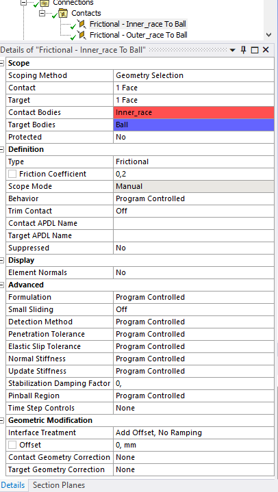
SubscriberYes, in case of FSI, since the ball and races are not in contact mechanically, there is NO contact definition assigned.
-
-
October 23, 2024 at 8:32 am
Rahul
Ansys EmployeeTry keeping the contact definition as is. It models a true gap as you are not providing any offset here. Using this setting will not close gaps.
Check 9.6.3.5. Geometric Modification for more info.
-
October 23, 2024 at 8:40 am
-
October 23, 2024 at 8:44 am
Rahul
Ansys EmployeeChange it to frictionless contact type as they not touching each other.
-
October 23, 2024 at 8:55 am
ashishkumar.gupta
Subscriberok I will Manually assign Fritionless contact
-
-
October 23, 2024 at 8:50 am
220512119
SubscriberNegative volume error, make sure the mesh mesh in fluent has an orthogonal mass of more than 0.2, and then try to lower the step size again
-
October 23, 2024 at 9:21 am
ashishkumar.gupta
Subscriber
-
-
October 23, 2024 at 9:27 am
Rahul
Ansys EmployeeOkay. In that case, try using the gap model in Fluent with Flow modeling as discussed in this tutorial: Reed Valve FSI Co-Simulation with Partial Setup Export from Workbench (Fluent-Mechanical)
You can find info about gap model in user guide here: 6.8. Controlling Flow in Narrow Gaps for Valves and Pumps
-
October 23, 2024 at 1:47 pm
ashishkumar.gupta
Subscriber-
October 24, 2024 at 7:26 am
ashishkumar.gupta
SubscriberHi Rahul, any insights on this?
-
-
-
October 24, 2024 at 9:35 am
Rahul
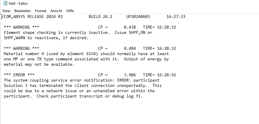
Ansys EmployeeSame problem? negative volume error or inner race not moving correctly?
As you have a very small gap between the race and the ball, it makes the setup difficult. Also, the mesh is moving in that zone, so it must be handled very carefully.
This setting specifies the minimum distance to be maintained between the faces of the moving bodies equal to the current gap size. This will prevent the fluid mesh from collapsing by preventing the ball from interpenetrating the race (you can try specifying the offset = gap size).
Here Fluid flow(CFX) uses the CFX solver
Fluid Flow(Fluent with Fluent Meshing) uses the Fluent solver and Fluent Meshing mesher is used to mesh the geometry
Fluid Flow(Fluent) uses the Fluent solver and geometry is meshed with Ansys WB Mesher
Fluid Flow(Polyflow) is not for case.
You can use Fluid Flow(Fluent with Fluent Meshing) or Fluid Flow(Fluent).
-
October 24, 2024 at 9:40 am
ashishkumar.gupta
Subscriber-
October 24, 2024 at 12:27 pm
ashishkumar.gupta
Subscriber
-
-
-
October 24, 2024 at 12:58 pm
Rahul
Ansys EmployeeAgain, I would recommend you check the BCs.
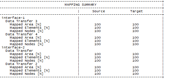
There should be 3 surfaces (Coupling Interfaces) across which Fluent and Mechanical would exchange the data i.e. inner race, outer race, and ball surface.-
October 25, 2024 at 6:22 am
-
October 25, 2024 at 10:33 am
ashishkumar.gupta
SubscriberHi Rahul, Any update? I have checked my BCs but I do not seem to find any error.
Please help me out with this!!
-
-
October 25, 2024 at 6:21 am
ashishkumar.gupta
Subscriber.
-
- You must be logged in to reply to this topic.


-
4979
-
1650
-
1386
-
1242
-
1021

© 2026 Copyright ANSYS, Inc. All rights reserved.

