
-
-
April 29, 2022 at 3:45 am
ali_elsharkawy
SubscriberApril 29, 2022 at 7:31 pmSean Harvey
Ansys Employee
Based on what you shared, you have auto time stepping as program controlled. For this type of large deformation, large strain it won't be ideal. Change to on, then set the initial, min and max substeps to break up the loading into smaller substeps. In this type of rolling simulation, you won't want more than a few degrees per substep, so set your initial substep so that over the time for that step, you are not rotating more than 1 or 2 degrees. Then for max substeps, set it even large if the solver needs to bisect, which it will. Don't be afraid to set the max substeps 10x higher than initial for this case. The min substeps gives you control so you get at least so many substeps which helps with smooth results reporting, etc.
Also, be sure your contacts are set properly to frictional with a realistic coefficient of friction.
See if this helps you get further.
Thanks!
Sean
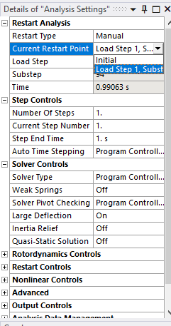
April 29, 2022 at 8:15 pmSubscriber, the problem is I do not have control over sub-steps
it is either automatic control or manually, in manually I have two options:
values program defined
set to initial
April 29, 2022 at 8:34 pmSubscriber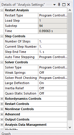
April 29, 2022 at 9:14 pmAnsys Employee
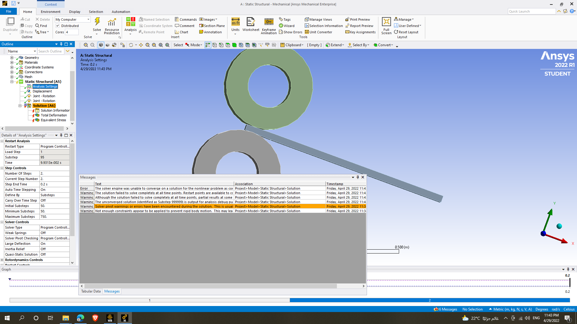
So right now you are trying to restart the simulation. You want to right click on the solution branch and clear the generated data. Then you will be starting a new simulation, not a restart. Please try that.
Regards Sean
April 29, 2022 at 9:44 pmSubscriberI did as you said and the process failed in 50% of the simulation :(((
April 29, 2022 at 9:56 pmAnsys EmployeeThat is progress! This is a nonlinear simulation. It will take some effort to get a viable solution. You are using 1 element in the thickness direction of your sheet. Unless this is a solid shell element, it won't capture the plasticity. You should set a mesh size to give at least 4 to 6 elements (as a start) in the thickness and keep your aspect ratios from being excessive.
You should check out these courses on plasticity which will help.
Convergence Problems in Metal Plasticity | Ansys Courses
Metal Plasticity | Ansys Innovation Courses
In this last course in the simulation examples, there is a cold rolling problem that is very similar.
Best of luck and let us know after looking at this content if you are stuck.
Regards Sean
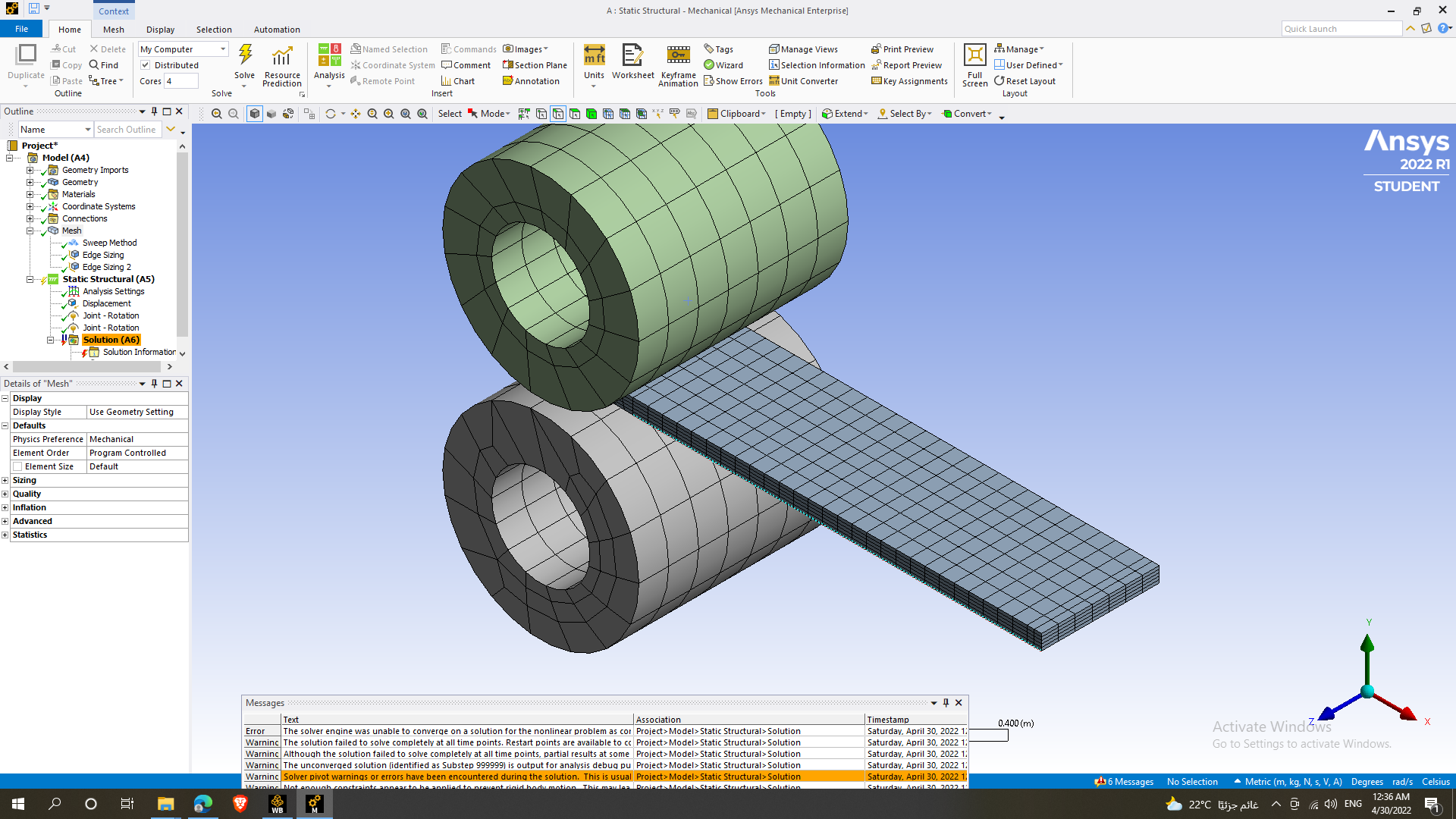
April 29, 2022 at 10:36 pmSubscriberI made them 5 elements and still the same error :((
April 30, 2022 at 1:33 amAnsys Employee
You should have two contact bodies. In the details set behavior to asymmetric. Then make sure the workpiece has the contact surface and the roller has the target. Do this for both contacts. What do you have for initial, min, max substeps? How much rotation is specified on the rollers?
Thanks
Sean
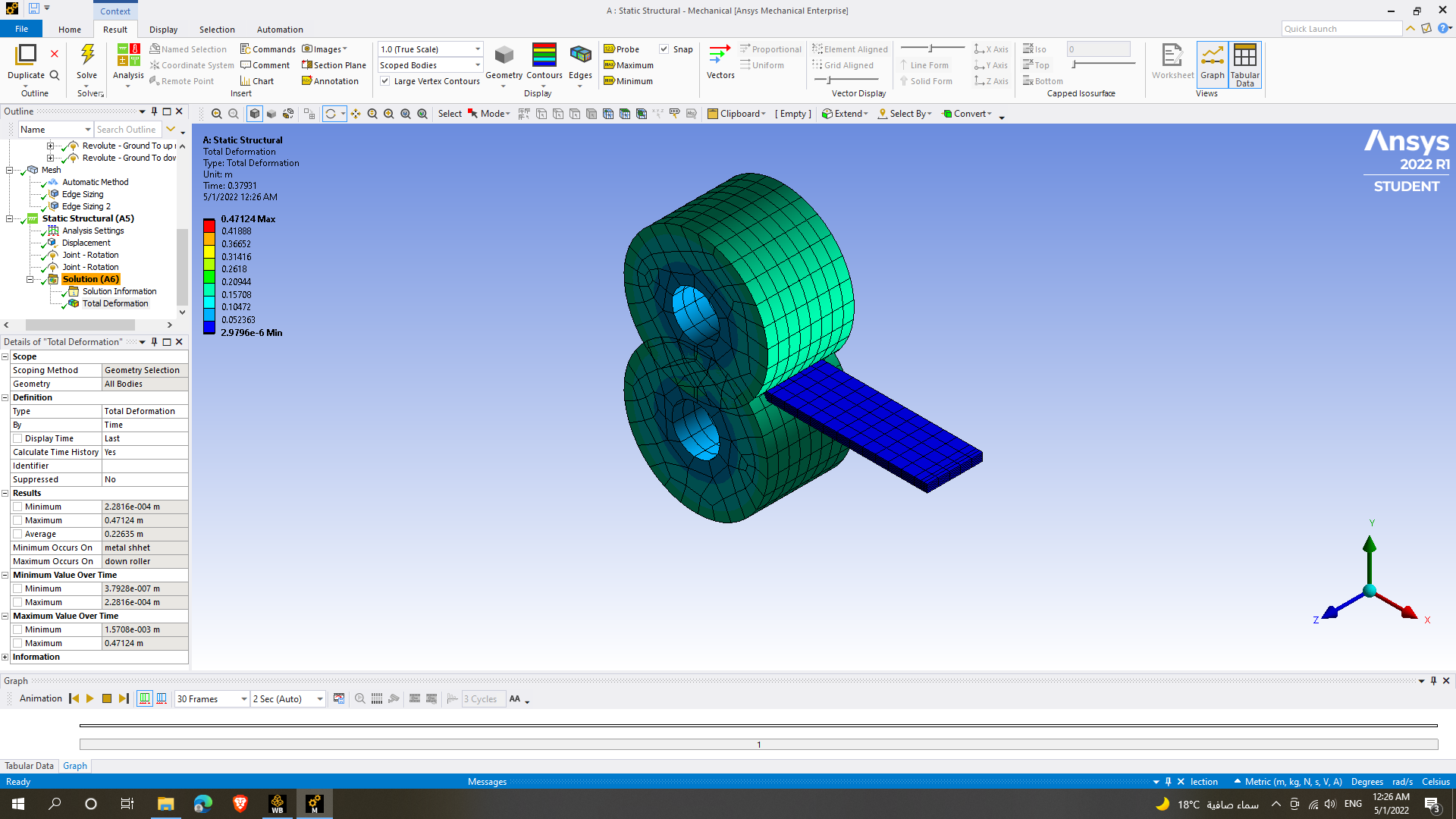
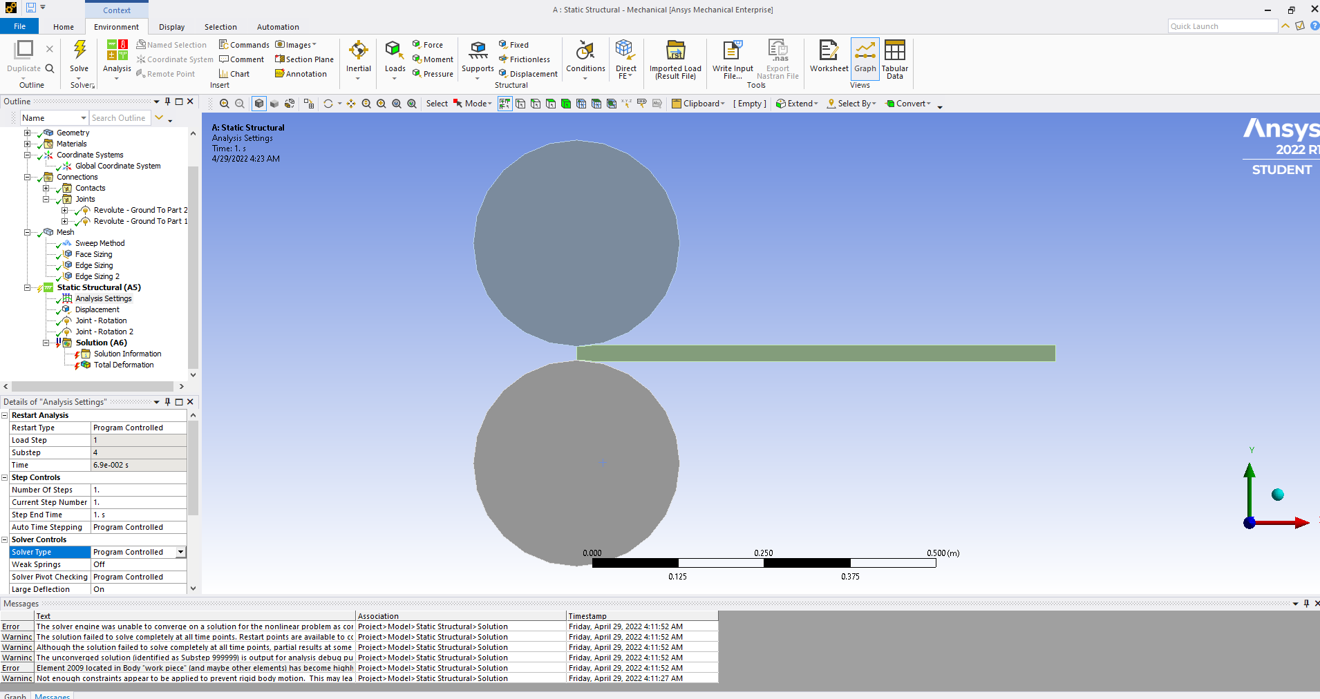
April 30, 2022 at 10:40 pmSubscriberso sorry for being late I had some problems, so I redesigned the model and set the behavior to asymmetric and the rollers to rigid bodies with initial and minimum substeps of 300 and maximum of 750 and I got the same problem: The solver engine was unable to converge on a solution for the nonlinear problem as constrained.Please see the Troubleshooting section of the Help System for more information.
and got this new one :
Large deformation effects are active which may have invalidated some of your applied supports such as displacement, cylindrical, frictionless, or compression only.Refer to Troubleshooting in the Help System for more details.
when turning large deflection off and trying to solve there are no errors but the roller rotates as it eats the material :((
May 1, 2022 at 1:32 amSubscriber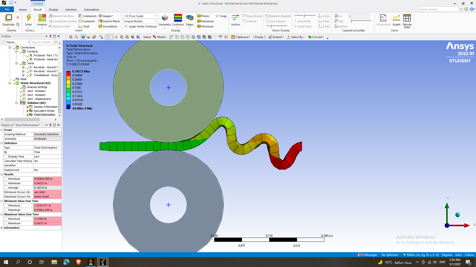 after replacing the displacement with a displacement joint I got this and without it, the workpiece Just moved a little bit in the roller direction then in the other way in X axis
May 2, 2022 at 1:43 amAnsys Employee
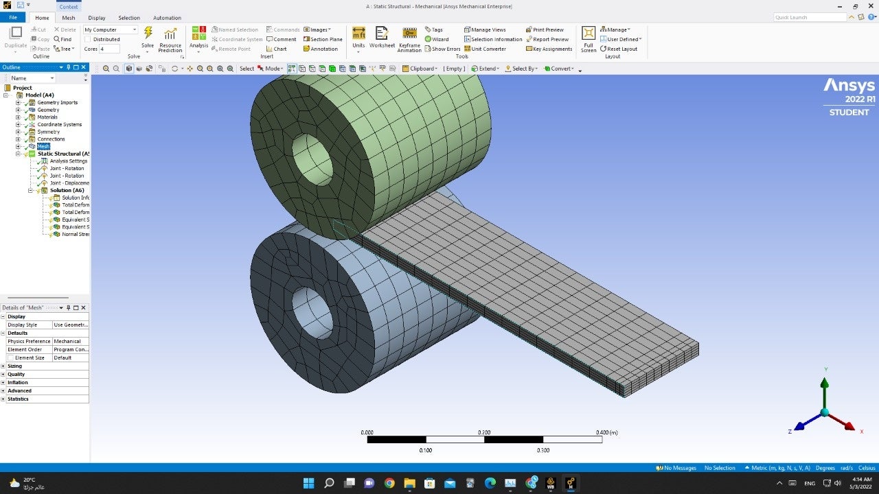
You will need large deflection on. This is not a small deflection problem. The latest images you show only have 1 element in thickness direction.
One suggestion that can help is to run the model as 1/2 symmetric. We can assume that the rolling process will affect the sheet equally in +y as -y, provided we ignore effects like gravity which are likely small.
You cut the sheet in the xz plane and model only the +y or -y region. At the symmetry plane, you can apply a frictionless support which will not allow the nodes to more on that plane in y direction, but they can move in x and z. This will help to stabilize the problem. Also, since you are using student version, you can now put a finer mesh in the x and z directions and not hit the node limit of the free student version. You still will want maybe 2 to 4 elements in thickness direction to capture the plasticity, but this does not mean you won't need more. That would come from performing a mesh convergence study.
One other option is to go to the behavior on the roller, and change it to rigid. Then you can scope the joint or remote displacement to the inside of the roller to impart the rotational motion. You can make the mesh on the roller a bit finer too. When we make the body rigid, Mechanical meshes the contact surface, but does not mesh the body since we have told it to use a rigid behavior. This assumption is good when we don't expect deformations in the tooling. I don't know if this assumption is valid for you model, but in many rollering problems, where the workpiece has a lower yield than the tooling it is.
Please try these suggestions.
Best of luck!
Regards Sean
May 2, 2022 at 6:05 amSubscriberHi, MR first of all I want to thank you very much for helping me you really helped me to understand very much :)
second, I still facing a problem
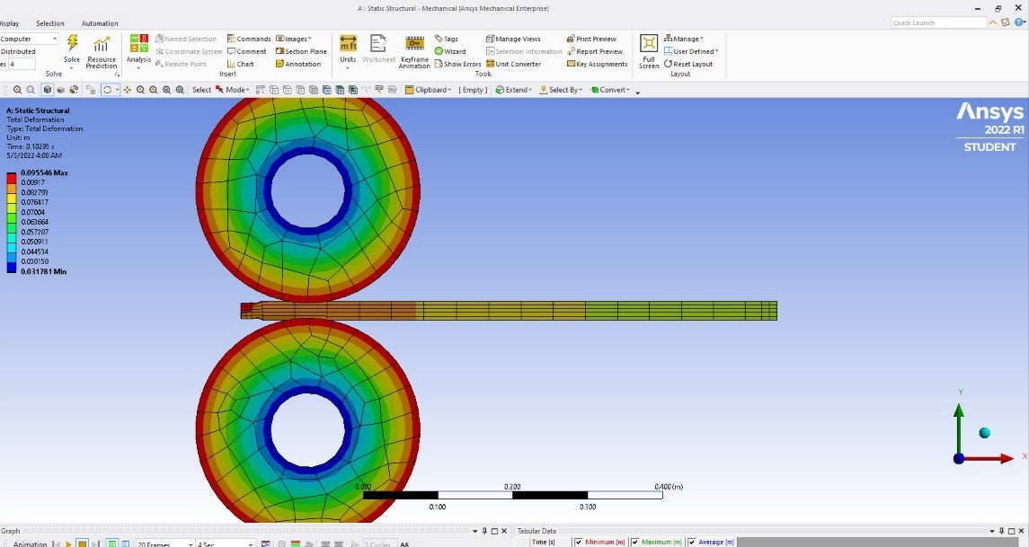
in the deformation, the sheet is still not deformed it is deformed when it is between the rollers only then in the exit the sheet return as the initial height
May 2, 2022 at 6:09 amSubscriber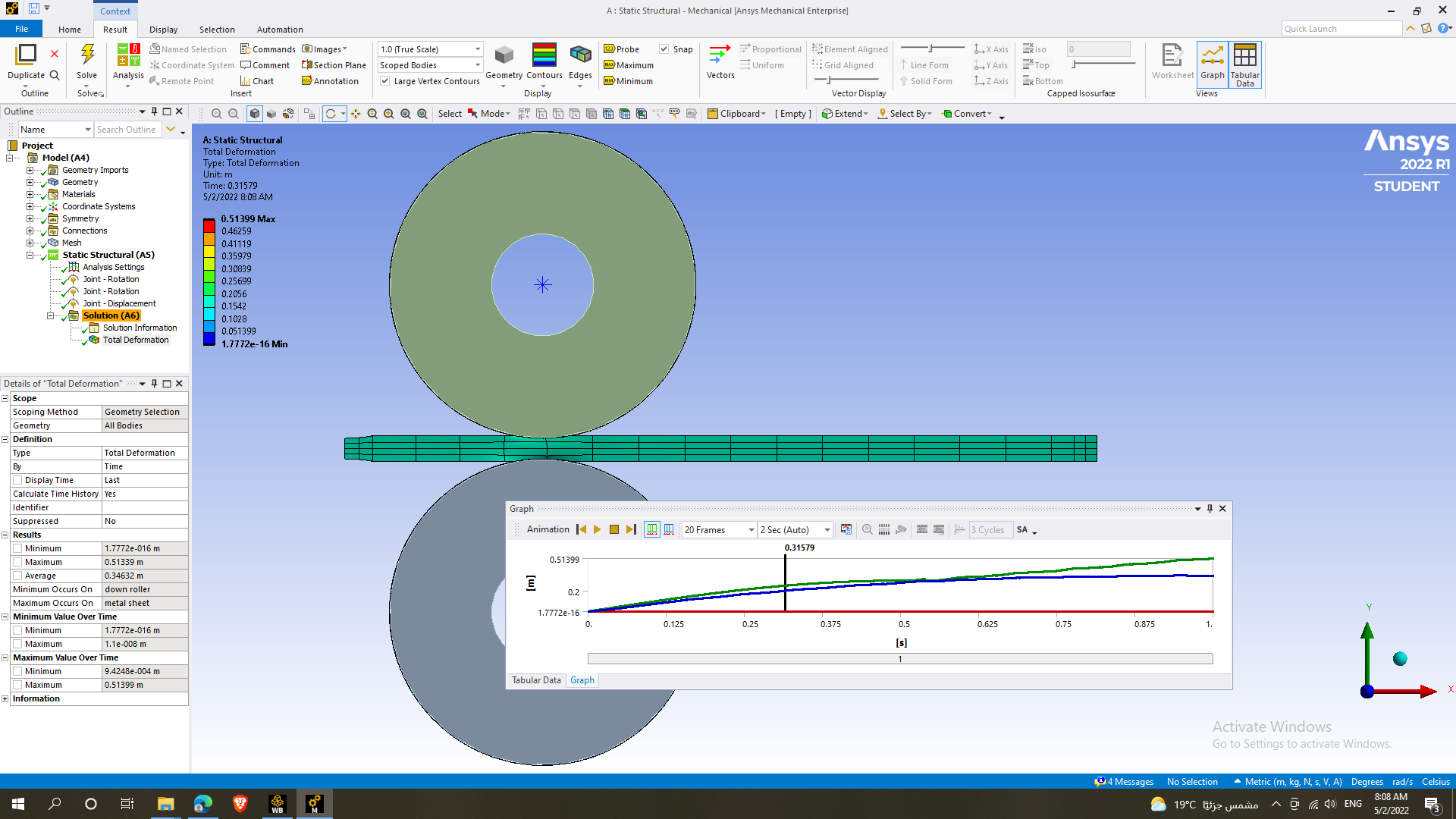
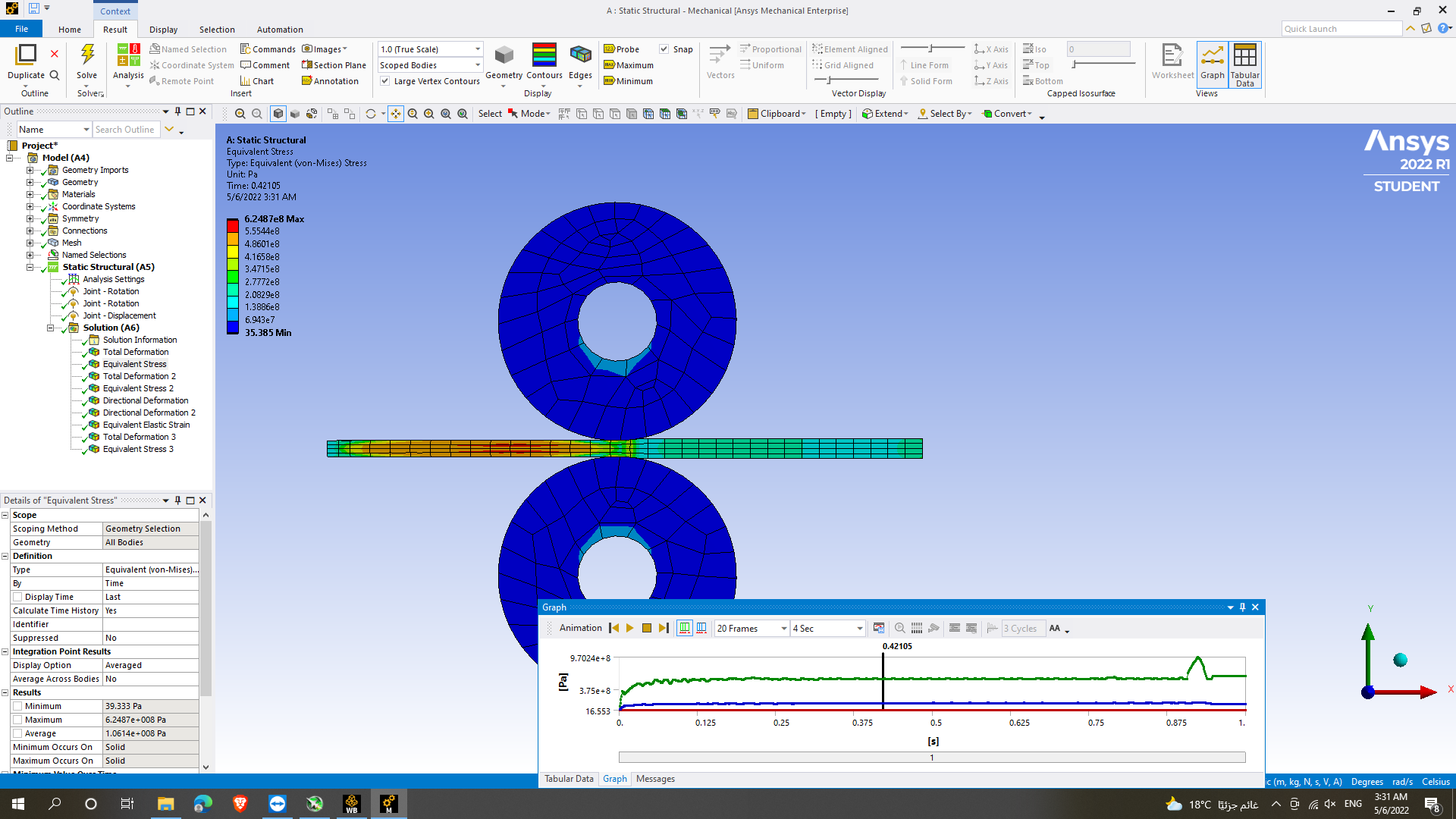
May 2, 2022 at 9:10 amSubscriberAnd when I change roller to flixable bodies to calculate the total stresses over then there is no change of thickness even in the thickness between the rollers
May 2, 2022 at 4:51 pmAnsys Employee
You are welcome. So, for your material, have you included a plasticity material model in engineering data? You will want to post-process plastic strain to give an indication of how much plastic straining is taking place. Also, your mesh density in the x-direction is way too coarse. You need to make the at least 4 to 8 times finer in-plane (x-z).
Regards Sean
May 3, 2022 at 3:03 amSubscriberI made the mesh finer in (x-z) and changed the material to aluminium alloy and still the same problem :((
May 3, 2022 at 4:57 amAnsys Employee
Are you sure you have a material with a plasticity model, for example, aluminum alloy NL from the engineering library. You need to be sure you have a plasticity model properly defined.
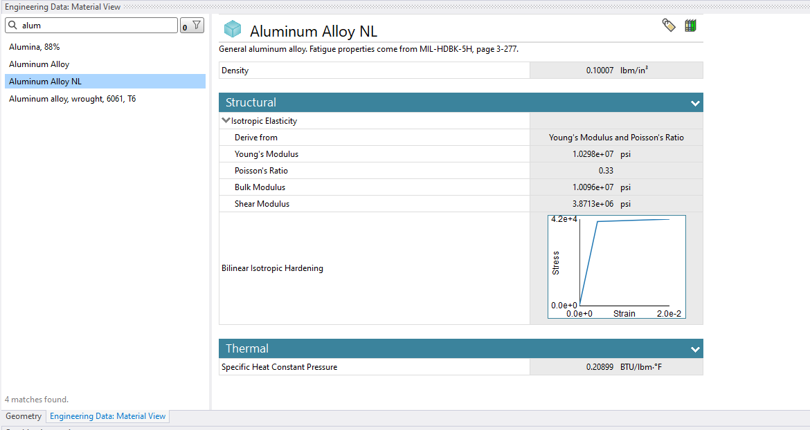

May 3, 2022 at 5:08 amAnsys Employee
Notice that this material has a bilinear isotropic hardening model.
Regards Sean
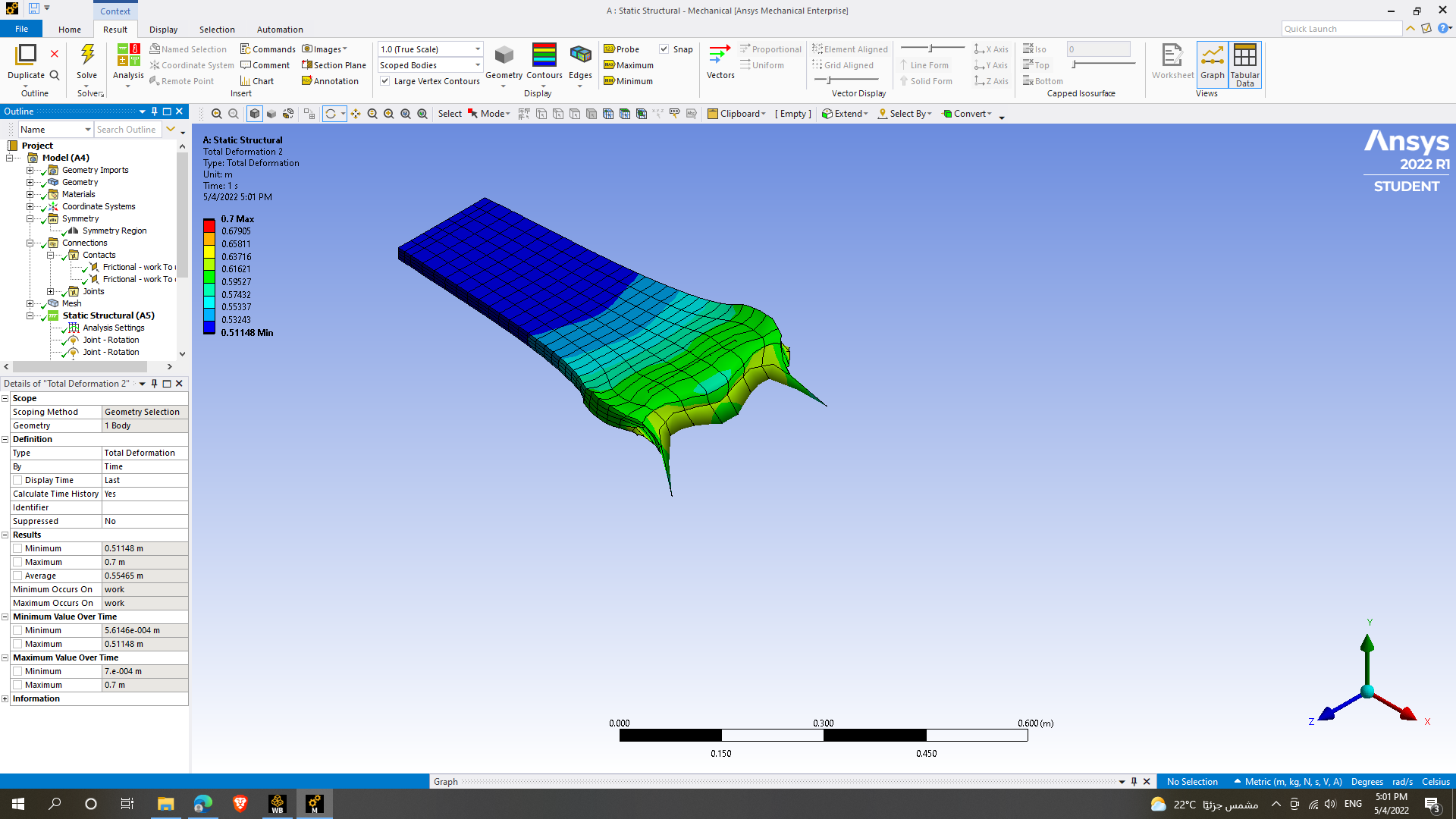
May 4, 2022 at 3:02 pmSubscriberso sorry for bothering you
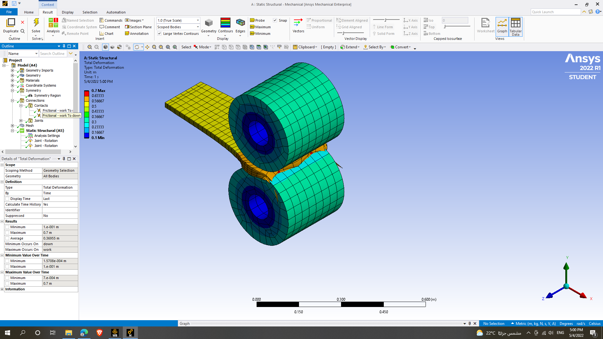
I have changed the material to copper alloy and the plasticity model properly defined but the deformation occurs in the z-direction instead of the x-direction how can I solve this problem
May 4, 2022 at 4:01 pmpeteroznewman
SubscriberRollers should always be wider than the material being rolled.
You should take advantage of Symmetry. already mentioned 1/2 symmetry using a plane at half the thickness of the material and using a single roller. I suggest 1/4 symmetry by adding a plane at half the length of the roller so the material is only half as wide.
May 4, 2022 at 5:41 pmAnsys Employee
What notes is a great suggestion as I had indicated on symmetry. I had not indicated that the roller should be wider. Thanks Peter.
Your mesh is still too coarse on the plate, so consider going even finer.
Regards Sean
May 4, 2022 at 9:56 pmSubscriberthe thickness of the roller is 280 and the thickness of metal sheet is 180 it doesn't make sense that elongation in z- direction be that value
May 4, 2022 at 9:58 pmSubscriberAnd also Ôêålength is too small and it doesn't make sense either
May 4, 2022 at 10:03 pmSubscriberDon't pay attention to results from models that are not behaving well.
Update the model using the 1/4 symmetry then we can talk.
It's also important to take small steps, so both the Initial and the Minimum Substeps should be large numbers (or the Time Increment should be small if using Time).
May 4, 2022 at 11:44 pmSubscriberCan you help me understanding how to add plane of symmetry
I did it before but by choosing a surface and add system region using the normal direction as the symmetry normal
Is that the way it should be or there is other feature I don't know about it
Sory for bothering
May 4, 2022 at 11:57 pmSubscriberMay 5, 2022 at 12:20 amSubscriberIn SpaceClaim (or DesignModeler) insert a Plane and cut the geometry in 1/2 and delete 1/2 the solids. Repeat with another plane.
In Mechanical, insert a Symmetry folder and insert under that a Symmetry Region and select all the cut faces for one of the planes and set the Coordinate Axis that has the Normal vector to that plane. Repeat for the other plane.
Instead of using Symmetry, you can just select all the cut faces and Insert a Displacement and set the normal to 0 leaving the other two Free. Repeat for the other cut plane. This is exactly the same as using Symmetry.
May 5, 2022 at 12:59 amSubscriberWOOOOOOOOOOOOOOOOOOOOOOOOW it really worked
the deformation made sense
this time
how can I show the whole process not only one section, please
May 5, 2022 at 1:00 amSubscriber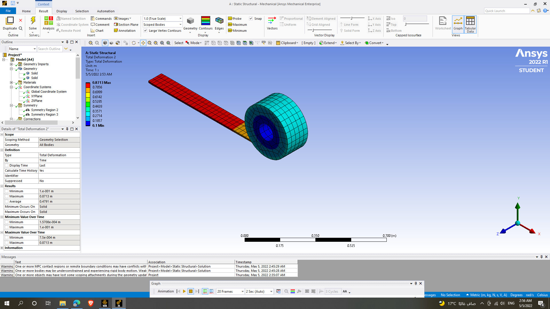
May 5, 2022 at 1:04 amSubscriberMay 5, 2022 at 4:03 pmAnsys Employee
Let me share some screenshots. One moment please.
Regards Sean
May 5, 2022 at 4:34 pmAnsys Employee
Congratulations. We have a video on symmetry Understanding When to Take Advantage of Symmetry Using Ansys Mechanical - YouTube
If you go to time 16:21 it explains how to graphically expand the results using beta options. Please try that.
Regards Sean
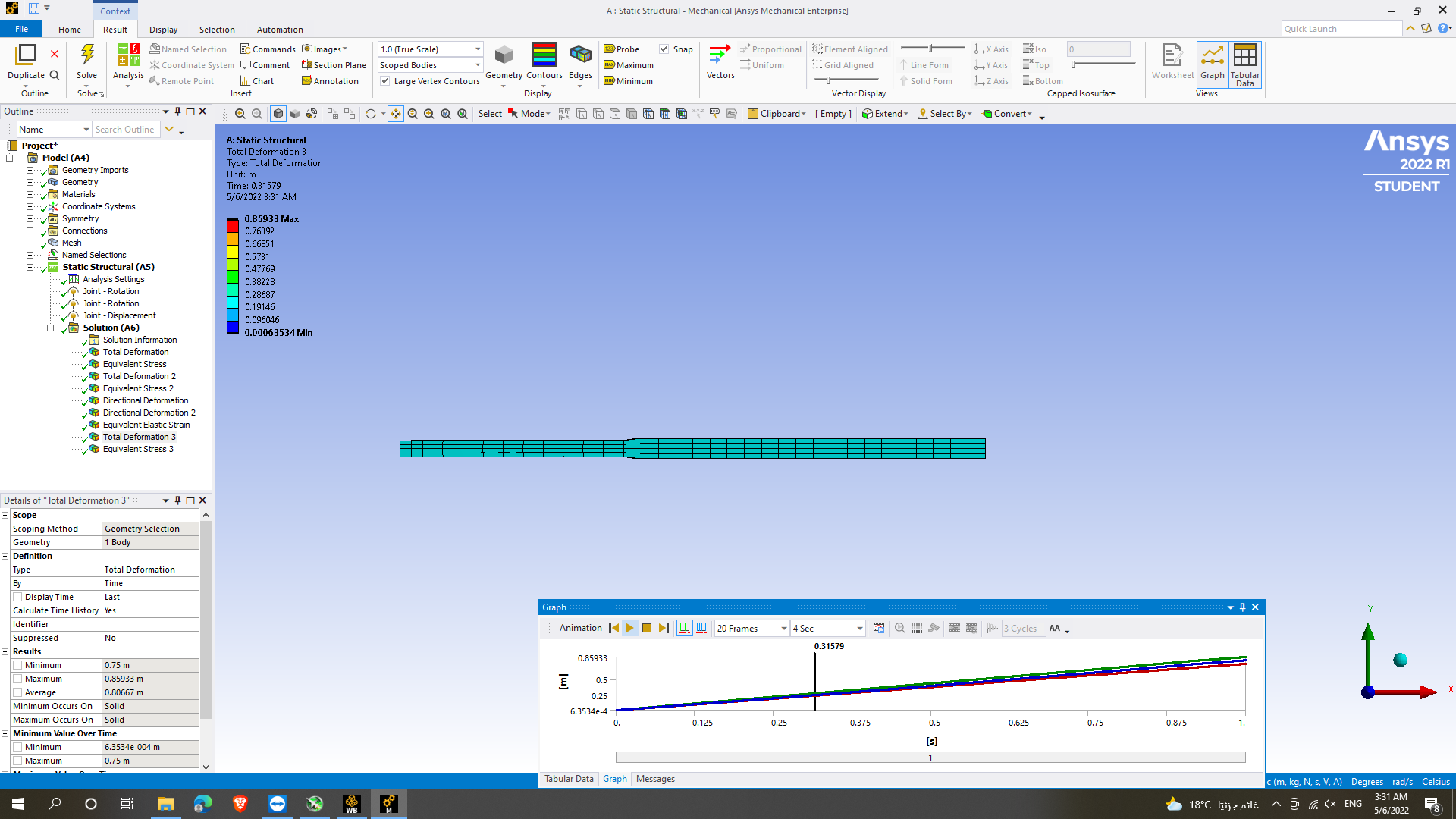
May 6, 2022 at 1:42 amSubscriberIt finally worked after long days and hours
Thank you for all help and support you gave me i really appreciate this help and your effort


May 6, 2022 at 2:31 pmAnsys Employee
Congratulations!
Regards Sean
Viewing 34 reply threads- The topic ‘2 errors in rolling process calculation’ is closed to new replies.
Ansys Innovation Space Trending discussions
 Top Contributors
-
peteroznewman
 3727
3727 -
scabo
 1328
1328 -
Dennis Chen
 1163
1163 -
javat33489
 1090
1090 -
Shyam Prasad V Atri
1014
Top Rated Tags
© 2025 Copyright ANSYS, Inc. All rights reserved.
Ansys does not support the usage of unauthorized Ansys software. Please visit www.ansys.com to obtain an official distribution.
-


The Ansys Learning Forum is a public forum. You are prohibited from providing (i) information that is confidential to You, your employer, or any third party, (ii) Personal Data or individually identifiable health information, (iii) any information that is U.S. Government Classified, Controlled Unclassified Information, International Traffic in Arms Regulators (ITAR) or Export Administration Regulators (EAR) controlled or otherwise have been determined by the United States Government or by a foreign government to require protection against unauthorized disclosure for reasons of national security, or (iv) topics or information restricted by the People's Republic of China data protection and privacy laws.


