TAGGED: ansys-hfss, hfss
-
-
September 15, 2024 at 2:51 am
spate035
SubscriberHi,
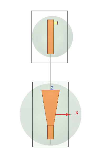
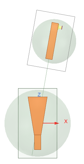
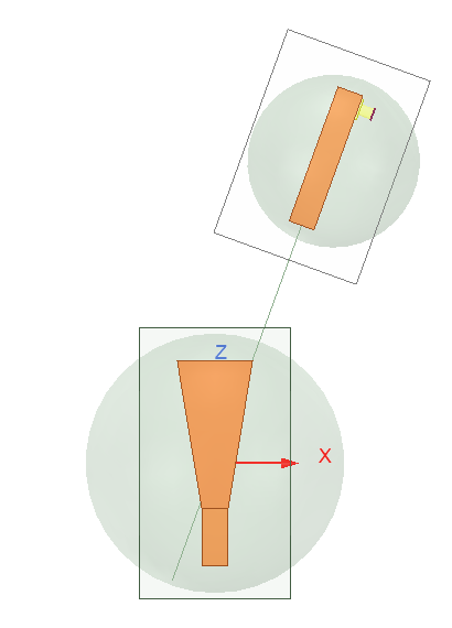
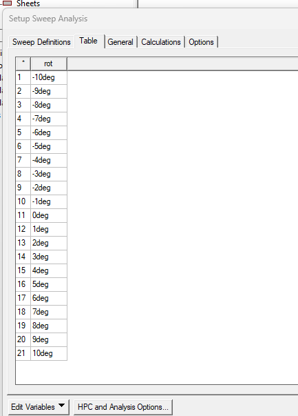
I'm running a parametric sweep by rotating a probe around a central horn antenna. I'm showing a few images below for illustration.
Fig 1: At Theta = 0 degrees.
Fig 2: At Theta = 10 degrees
Fig 3: Theta = 20 degrees
...And so on...
When I measure the phase of the S21 results, I see random 180 degree shifts in the measurements. I am not able to see any pattern in these shifts either.
I thought perhaps it was because I was initially using 2 FE-BI boundaries and that might be causing an issue. So I tried a single Radiation boundary instead, but that also didn't help.
theta_rotation [deg] S21 Phase Results [deg] -10 101.2924367 -9 103.7009139 -8 105.601412 -7 107.5837877 -6 109.0814497 -5 110.6225511 -4 -68.19983945 -3 112.7819268 -2 -66.46548137 -1 -65.96723292 0 114.1349591 1 114.08219 2 113.6846084 3 -66.93414481 4 112.1847997 5 111.1811682 6 109.7736687 7 -71.78552943 8 106.3168243 9 104.558732 10 102.4050767 As you can see from these results, at random points the phase shifts down by ~180 degrees.
For example at Theta = -4, the phase measurement is -68.2 degrees, whereas at Theta = -5 it is 110.6 degrees, and at Theta = -3 it is 112.8 degrees. The -68.2 measurement seems to be shifted down by 180 degrees (-68.2 + 180 = 111.8). 111.8 degrees seems like a more reasonable measurement. This occurs again at random points with no discernible pattern.
Can I please get some feedback on why this issue might be occuring and how I can fix it?
Thank you,
Shyam
-
September 20, 2024 at 4:25 pm
David Prestaux
Ansys Employeedid you calibrate the ports by specifying integration lines at the port? this may be the cause.
-
September 21, 2024 at 4:41 pm
spate035
SubscriberYes, I have defined an integration line on both ports.
-
-
October 4, 2024 at 8:03 am
David Prestaux
Ansys EmployeeHello, radiation boundary for the whole structure or around each of the horn? it will only work for the whole structure.
I think maybe you see some difference because you are not maintaining the same distance between the antenna as you rotate. Have you tried it with short or small distance? at short distance, this may not be obvious to define the rotation around the phase center of the antenna which would be close to the center. In summary, I don't see any reason why the results you're getting should be wrong and given that you created the integration line and converged well....you can check the convergence of the S21 phase to see its variation...you are getting the correct result.
-
October 4, 2024 at 8:53 am
-
October 5, 2024 at 4:32 am
spate035
SubscriberHi David,
Regarding the radiation box, I meant I tried a single radiation box encapsulating both antennas, as well as a separate simulation where I had the two antennas in individual FEBI boundaries.
I am maintaining the distance between the antennas as I rotate. I have tried a short distance... actually the distance between the two spheres (the ones the antennas lie in) is 150mm. As I'm simulating at roughly 10GHz, the antennas are only about 5 wavelengths apart.
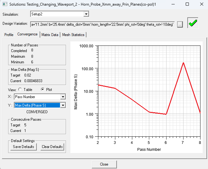
Regarding the convergence, I've taken a look, and it seems that the convergence from one adaptive pass to another can jump up by 180 degrees. If you take a look at the below image, at -10degrees, the simulation seems like it will converge near -79degrees, but then at adaptive pass 7 it shoots up by 180.
Convergence shoots up at pass #7, which is again where the change from -79 to 101 occurs as highlighted above, and then it settles back down.
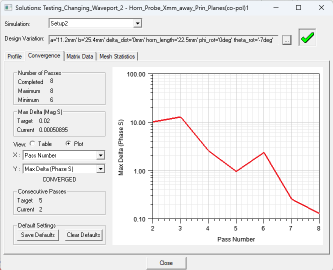
And then if you take a look at the first image again and consider the theta_rot = -7degrees case, the value always remains around 110degrees for all 8 adaptive passes. And the convergence doesn't shoot up as we see in almost every other case.
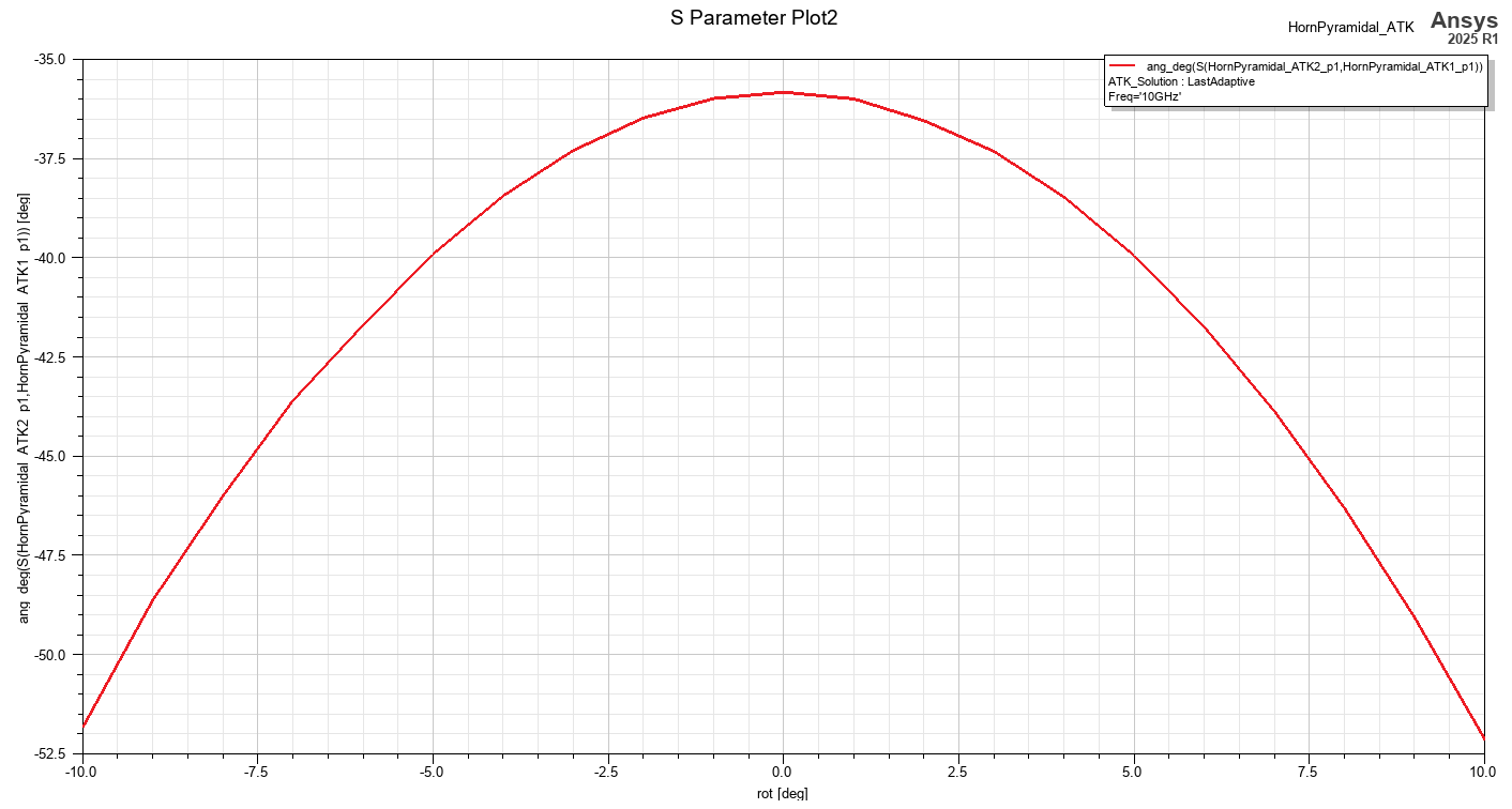
I see that you are not having the same issue as I am from the S-parameter plot you posted. So maybe I need to do something special regarding the mesh? I have not changed anything regarding the meshing from the default settings. I'm not quite sure what you mean by "mesh asembly used and mesh is preserved in the parametric sweep to avoidn numerical noise:". How can we use mesh assembly, and is it available in 2021.R1 version? And how did you "preserve the mesh in the parametric sweep?"
Thank you,
Shyam Patel
-
October 5, 2024 at 8:07 am
David Prestaux
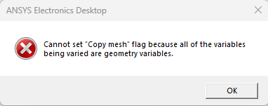
Ansys Employeethe jump is very likely due to the integration being swapped so the 180deg jump. in the classic way, you would visualize the vectors. be sure the integration is working well at a few angles . the more certain way in you scenario is using mesh assembly. an example being shipped with the install under the antenna is doing mesh assembly with horn feed and dish antenna . the second step is to keep the mesh for all variations in the parametric sweep ( last tab). it would much easier for you to be under the latest release and also share the design in the classic support I would think.
-
October 5, 2024 at 8:05 pm
spate035
Subscriber
-
- You must be logged in to reply to this topic.


-
5094
-
1831
-
1387
-
1248
-
1021

© 2026 Copyright ANSYS, Inc. All rights reserved.

