TAGGED: coil-design, coil-terminal, different-solution, eddy-current, terminal, winding
-
-
April 17, 2023 at 8:21 am
Lukas Hildebrand
SubscriberHello Everyone,
I want to add coils to a model which are short circuited in an EddyCurrent simulation.Â
Without a terminal or Winding, the solution is realistic but in that case the whole area is regarded as solid copper.
When adding a 0V Excitation with a stranded Winding of 15 mOhm (Because apparently stranded windings need to have a resistance) or less and a terminal of N conductors, the solution does not differ from the setup without any SC-Conductors at all.
Can someone explain to me why this isn't working and how too add short circuitable coils to an EddyCurrent simulation so they are regarded properly?
Â
Thanks in advance and with kind regards,
Lukas
-
April 19, 2023 at 1:07 pm
DELI
Ansys EmployeeHi, could you please share more information about this simulation? could you please share a screenshot of the Maxwell design?
-
April 19, 2023 at 1:20 pm
Lukas Hildebrand
SubscriberHello Deyu,
Thank you for your answere. Here is a screenshot of the coil that I want to use as a Shortcircuit in my simulation (For now with one winding to compare against the case of no terminal at all)
The solutions of the primary inductance and the field inside the surrounded toroid differes heavily in both cases which is why I cannot use the terminal to assign more windings to the shortcut since the solutions are not comparable.
Please tell me if it is possible to insert short circuit coils in EddyCurrent simulation and if so, how to do it. Thank you in advance!
Â
-
April 19, 2023 at 2:32 pm
DELI
Ansys EmployeeHi Lukas, yes, you can use this setup as short circuit in Eddy Current solver. It's basically short the coil winding with the 15Ohm load resistor together.
With short circuit in the winding from above picture, the field will be different from solid copper object without coil terminal. Are expecting other behavior?
-
April 19, 2023 at 2:48 pm
Lukas Hildebrand
SubscriberYes, because it is just one winding, which would lead to solid copper again. I dont understand how ansys regards the number of windings of the terminal.
Also I tried to use this technique to determine the current in the short cirquit (see my other post: /forum/forums/topic/different-results-if-using-coil-terminal-in-shortcut/ ) but the setup behaved differently with the terminal of 1 conductor than without it.
I hope you understand my problem now and eagerly await your answer.
-
-
-
April 19, 2023 at 2:42 pm
Lukas Hildebrand
SubscriberYes, because it is just one winding, which would lead to solid copper again. I dont understand how ansys regards the number of windings of the terminal.
Also I tried to use this technique to determine the current in the short cirquit (see my other post: /forum/forums/topic/different-results-if-using-coil-terminal-in-shortcut/ ) but the setup behaved differently with the terminal of 1 conductor than without it.
I hope you understand my problem now and eagerly await your answer.
Â
-
April 19, 2023 at 2:53 pm
DELI
Ansys EmployeeHi Lukas, are both tickets the same transformer design? Is the goal calculating the inductance on the primary winding?
If yes, there are two primary coils, do those have excitation?
From the other post, you are drawing a separate close loop for the short circuits, are you adding short circuit on the primary winding for this post? What does the real test setup look like?Â
-
April 20, 2023 at 8:00 am
Lukas Hildebrand
SubscriberHey Deyu, thank you for your continuous answers.
They both are for the same project, yes. Just this one regards another type of short circuit. The goal is to calculate the inductance of the primary windings, yes.
The two primary coils both have an current excitation with a stranded winding of <1A, and a terminal of N primary windings (E.g. 25)
Exacty, the secondary short circuits are seperated from the primaries. The primaries have the above mentioned excitation and no other.
I cannot send you the real test setup because it does not exist yet.
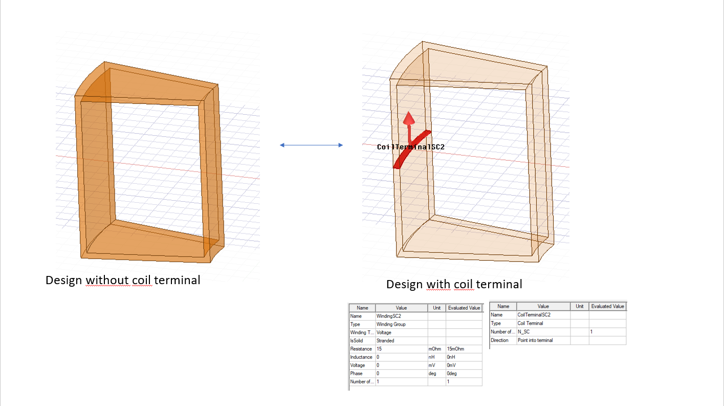
In general I am just wondering why the closed conductor path solid with a winding of 1 conductor behaves differently, than with no winding at all. That is the reason why I am not sure about the solutions reliability if the SC is simulated with more than 1 winding.
I hope my question is clearer now and thank you for your answer in advance!
-
April 20, 2023 at 2:17 pm
DELI
Ansys EmployeeHi Lukas, thanks for the additonal info. When there is no winding, it will just be eddy current on solid conductor. When you assigned winding on that conductor, there will be current flowing in close loop so fields are different.
-
April 24, 2023 at 12:55 pm
Lukas Hildebrand
SubscriberThanks for the answere, but the question kind of remains. Since the solid conductor is closed, the current will flow in a closed loop as well. How is that different from the current flowing in a winding with just 1 loop?
Also the result is completely different and just wrong if compared to real measurements. It seems that the windings have no impact on the solution at all (even tho the SCs are modeled with eddy current effects). In case of using no terminal the result is very accurate even for multi winding SC-coils (where each winding is actually modeled as a conductor).
This raises the question how a terminal with 0V excitation behaves since it clearly does not behave like the short circuit in this case...
-
-
-
- The topic ‘0V Excitation not working as Short Circuit’ is closed to new replies.
-
2863
-
970
-
851
-
599
-
591
© 2025 Copyright ANSYS, Inc. All rights reserved.