Ansys Learning Forum › Forums › Discuss Simulation › 3D Design › Fillet Fix, Double lines, Support, Lateral Bracing › Reply To: Fillet Fix, Double lines, Support, Lateral Bracing
Hi Sam,
1. Expand the Joint and select the Coordinate System under it then click on the Geometry line that says Click to Change and with the face filter, pick the two faces, then click Apply. The coordinate system will jump to the centroid of the faces.
2. Draw a line on the face, create a linear pattern of that line along the face, use Projection to project all lines onto the face. See attached file. Its not a surface you are creating. You are making edges by breaking up one face of a solid into multiple faces.
3. Lateral bracing is only needed on one side or the other, not both since it is to prevent the whole structure from going sideways. If you are doing both sides you are over-constraining the structure.
You want a Remote Displacement on each edge, not one for all edges. All edges make a single point not go sideways and creates a spider of connection elements from that one point to all the edges. You want individual points on each edge that can't go sideways.
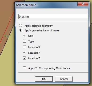
Make a Named Selection called bracing by clicking one edge then checking the Same Size, Y Location, Z location and it will find all 19 edges.
Create a Remote Displacement on one edge.
Use the Object Generator to automatically make the other 18 Remote Displacements.
5. I don't know what you mean. Maybe it's irrelevant due to the answers above?
Attached a new archive with Remote Displacements.
Regards,
Peter


