Ansys Learning Forum › Forums › Discuss Simulation › Fluids › Mass Conservation Issue in Methane Pyrolysis Shock Tube Simulation › Reply To: Mass Conservation Issue in Methane Pyrolysis Shock Tube Simulation
Hi Vijay
a) Are the walls adiabatic? Additionally, could you explain how energy conservation is managed across all three cases?
Wall are adiabatic for all cases
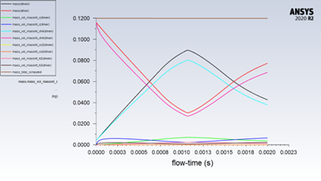
b) Could you provide a snapshot of the density contour for each of the three reacting cases, both before and after the point where the mass imbalance begins to rise?
Attached is the relevant snapshot.
c) If the CH₄ case were to run longer, would it also show signs of mass imbalance?
No mass imbalance appears in the CH₄ case as well as with reactions turned off, and it seemed to resolve the mass issue.
However, I conducted a test defining CH₄ as the gas on both the driver and driven sides (same properties but different names), with reactions activated only for CH₄ on the driven side. In this case, a drop in mass was observed.
CH4_driver and a CH4_driven
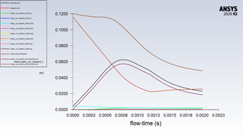
d) What Mach numbers are anticipated in the simulation? Could you also share the residual plots for either the H₂ or CO₂ case?
Theorically, we are xpected Mach numbers approximately 2.5 for CO₂ and 5.5 for H₂. (Attached are the residual plots.)
e) Could we attempt using a segregated solver with first-order (FO) schemes to assess any potential improvement in results?
I tested PISO, SIMPLE, and coupled schemes with CO₂ as the driver and CH₄ as the driven gas, using both first and second-order schemes. There are still drcomparison indicated no significant differences. I also experimented with inviscid models, applying no shear stress at the walls.
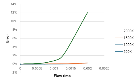
I tested various temperatures for the driver (CO2): 500, 1000, 1500, and 2000K. The results presented in the figure below( mass error over time) show an increase with higher temperatures, which suggests that the chemistry solver might be the issue.
Ghislain


