Ansys Learning Forum › Forums › Discuss Simulation › Fluids › Convergence issue in pipe flow › Reply To: Convergence issue in pipe flow
September 8, 2024 at 2:28 pm
Subscriber
Hello, I ran the simulation again in steady state with a better mesh quality and it converged. Turns out, my mesh quality was too poor to reach convergence. Now I have two more questions. Those are to check whether I am wrong or not. The fluid enters as irotaional flow in the inlet. But after the flow is hindered by the blind part of the pipe, small vortices are created in the inclined part (CD) (image 1). I wanted to measure that by using swirl number.
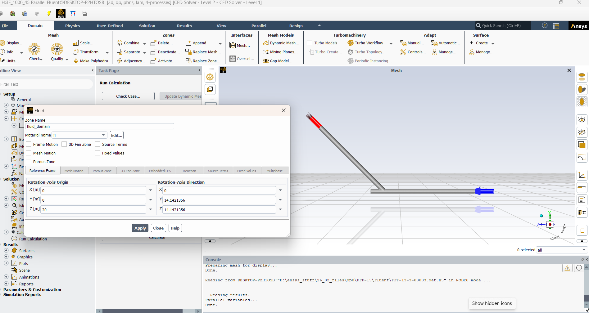
- So if I am to calculate swirl nummber in the CD part (20 meters) of ther pipe, please comfirm me if I have defined the rotaional axis properly (Image 2) ? I have defined my rotaional axis as the axis of the CD part of the pipe. Where the coordinate of C is (0,0,20) and of D is (0, 20*sin45, 20+20*cos45) or (0,14.142, 34.142).
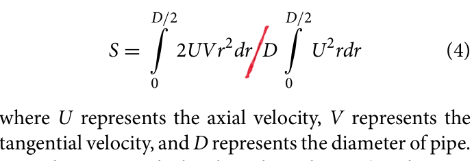
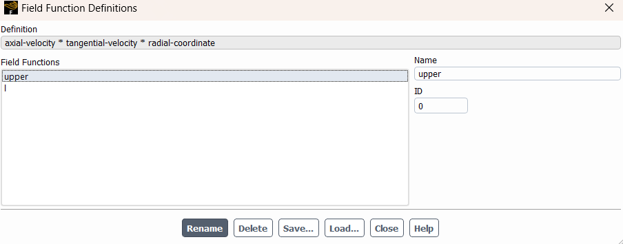
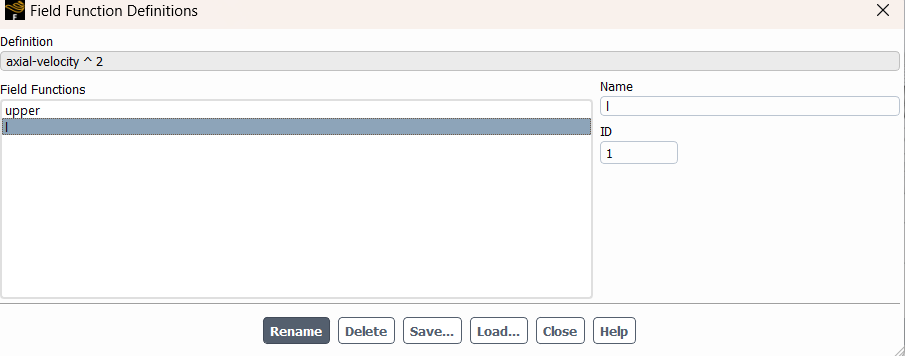
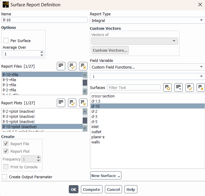
- The definition of swirl number says it's the ratio of axial flux of the angular momentum to the axial momentum (Image 3). Now, to measure the number, I have used the custom field function to define the intrgrand of the numerator and denominator (image 4,5). Then I integrated them in surface field report (Image 6,7). and finally determined the swirl number in (image 8). So, I was wondering if my process is right or not.

