Ansys Learning Forum › Forums › Discuss Simulation › General Mechanical › How to define a rigid surface for a solid › Reply To: How to define a rigid surface for a solid
August 8, 2024 at 11:44 am
Subscriber
Hi,
As you said, I set up the driver as a rigid body and created a remote point using its six sides.
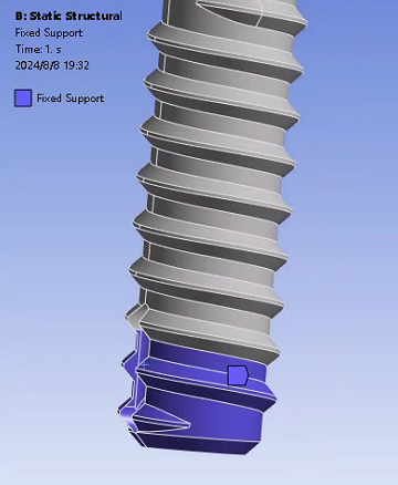
After that, I added a 0.1rad remote displacement of the Z-axis at the distal point, as shown in figure one. The bottom of the screw was fixed as shown in Fig. 2 and set frictionless.
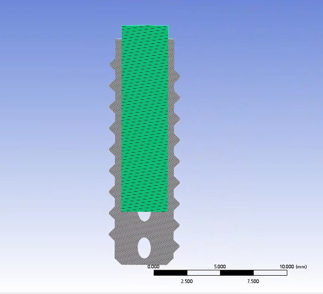
The profile of the geometry is shown in Fig. 3.
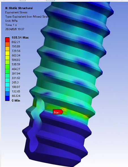
Figure 4 shows the equivalent mises stress of the screw.
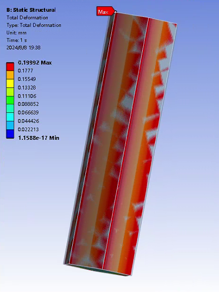
Figure 5 is a diagram of the total deformation of the drive section.
Figure 6 shows the value of the counter moment at the remote point.
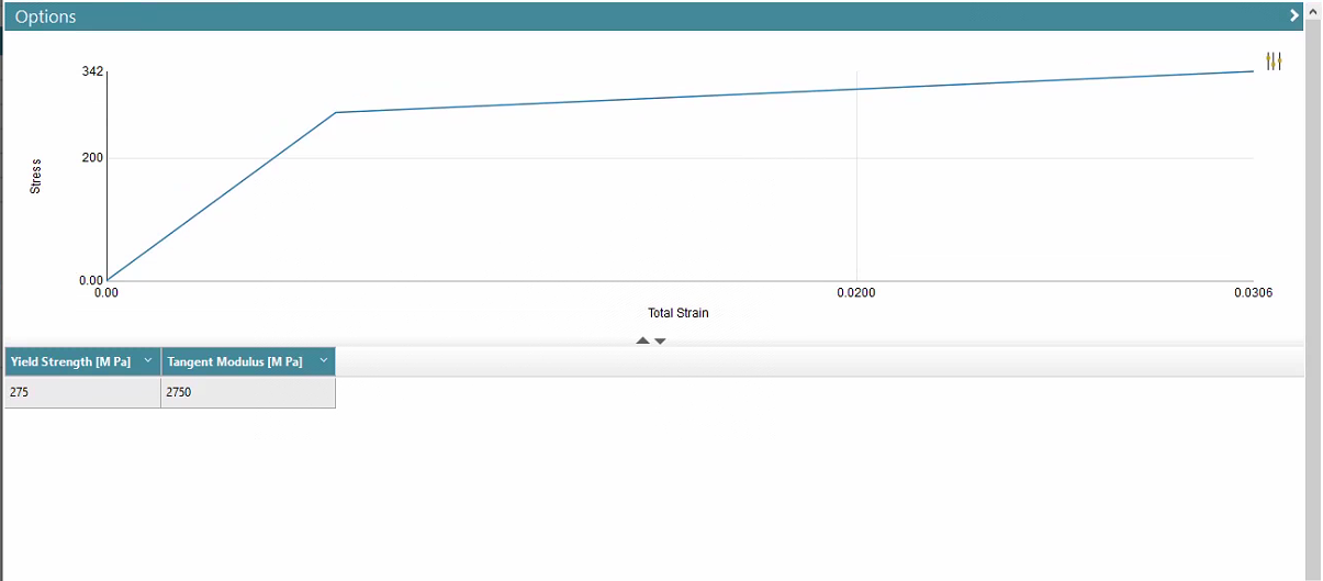
The same material properties are used for the transmission part and the screw as shown in Fig. 7, E is 45 GPa, v is 0.3.
I feel that this result is a little bit not reasonable:
The driver, being a rigid body, produces a non-negligible deformation.
The values of the equivalent force of the screw and the counter moment at the remote displacement seem to be too large. But I don't know where the problem is.
.

