Ansys Learning Forum › Forums › Discuss Simulation › Optics › Loss vs. waveguide bend radius in Lumerical FEEM › Reply To: Loss vs. waveguide bend radius in Lumerical FEEM
The structure simulated is a silicon rib waveguide. The mode 1 field (for straight waveguide) is shown along with the structure.
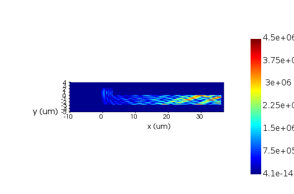
Bend waveguide simulation for a bent radius of 20 um is done. The field obtained is as below (for mode 1).
The substrate and slab x-span and z-span are taken as 40,000 um. The waveguide length is 40,000 um and is centered at x=0. The bend simulation region span was changed to xmin=-10 um to xmax= 36 um. Apart from xmin, remaining has a shell boundary condition, with shel thickess of 1 um. Bend location in FEEM is fixed as (0,0,0). Edges per wavelength = 5, and polynomial order = 4. No. of modes chosen are 2. Auto remove pml modes has been activated.
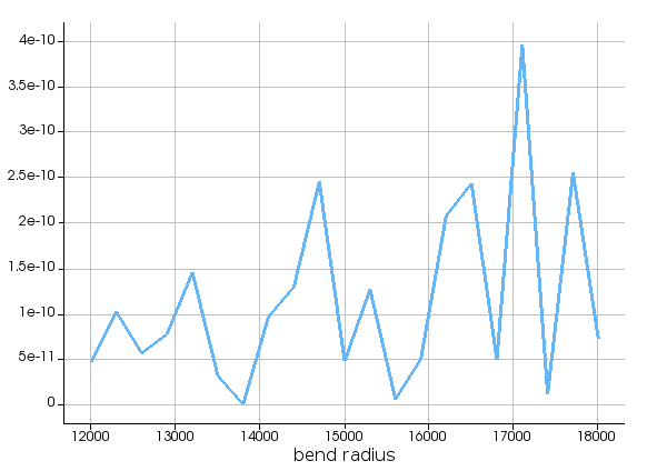
The bend radius is swept from 12,000 to 18,000 um. Both "mode properties" and "fields" are monitored.
1) One issue is the warning which says the fields returned are of different sizes.
2) The loss vs. bend radius plot obtained is shown below. I expect a gradual decrease in loss with increase in radius, which is not the case here.
3) The system used is of 64 GB RAM. I had monitored the memory usage during the simulation. Attached is the screenshot at an instance.
Please suggest what might be wrong here.
Thank you.


