Ansys Learning Forum › Forums › Discuss Simulation › General Mechanical › (Rolling) Sheet thickness after rolling doesn’t match the roller’s gap › Reply To: (Rolling) Sheet thickness after rolling doesn’t match the roller’s gap
Your deformation shows a max of 0.34mm on the revolute ground mount side of the rollers, and the other side looks about 0.26-0.29mm. It seems to be the purpose is to flatten and extrude the sheet (it should expand in the directions parallel to the sheet), so you would want a material that is a lot less stiff than the rollers or at least yields at much lower value. These 3 materials are fairly close in stiffness. Material 316 does have a lower yield strength. Have you checked if any of these materials are yielding? Do you have any other constraints on the sheet other than the symmetry or frictionless support? It seems to me in this process, you would want the sheet to yield but not the rollers.
Contact "target" side should be the flat plate, and contact "contact" side should be the convex surface, which is the wheel. Your image looks reversed in that regard.
Have you tried a penalty based contact, such as augmented lagrange, where you can adjust the normal stiffness factor?
Why are two rollers needed? This seems like an extrusion type of operation, and I would think you only need the one roller touching the plate.
It is true that a roller model will need very small element size on the wheel, and yours does look pretty small. But you could try even smaller to see how that affects the bouncing.
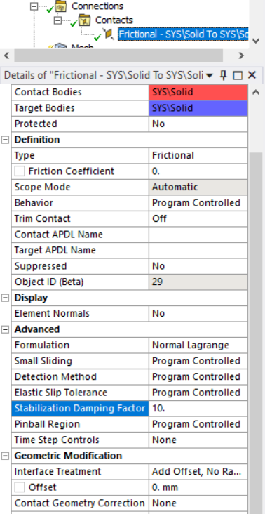
Set trim contact and small sliding to off.
Try a nonzero factor for "Stabilization Damping Factor" on the contact:
You may want to reduce the joint tolerance with an APDL command to allows less joint "chatter" within that distance. This may require smaller time stepping.
Undocumented JTOL argument:
SOLCONTROL, Key1, Key2, Key3, VTOL, JTOL Where, JTOL is used to specify the tolerance.
Currently the tolerance is set to: 1.E-07 ( an absolute tolerance value).


