Ansys Learning Forum Forums Discuss Simulation Electronics Negative stiffness in x-position between PM and steel stator Reply To: Negative stiffness in x-position between PM and steel stator

wrbulat
Ansys Employee

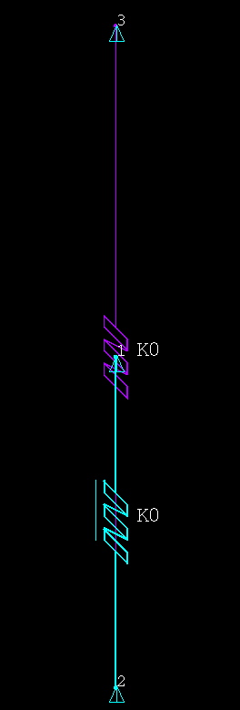
I'm not sure this is exactly what you're asking for, but I found this old MAPDL input file that uses two spring elements (COMBIN14 and COMBIN39) to posit nonlinear negative stiffness between two nodes (to mimic net magnetic force versus separation):

fini
/cle
 
/sys,del test_neg_K_05*.png
/fil,test_neg_K_05
 
/pnu,node,1
/pnu,type,1
/tri,lbot
/esha,1
/ics,1,5
/pbc,u,1
 
 
C***********************************
C*** MODEL
C***********************************
/prep7
 
n,1,,1 ! NODES
n,2
n,3,,2
 
et,1,39,0,0,2 ! NONLINEAR SPRING (COMBIN39) ATTRIBUTES
r,1, -0.5,10-1.25, -0.4,5-1.25, -0.3,3-1.25
rmore, -0.2,2-1.25, -0.1,1.5-1.25, 0,1.25-1.25
rmore,  0.1,1.10-1.25, 0.2,1.05-1.25, 0.3,1.03-1.25
rmore,  0.4,1.02-1.25, 0.5,1.015-1.25
 
et,2,14,,,2 ! LINEAR SPRING (COMBIN14) ATTRIBUTES
r,2,1.25/50
 
type,1 ! SINGLE NONLINEAR COMBIN39 ELEMENT
real,1
e,2,1
 
type,2 ! SINGLE LINEAR COMBIN14 ELEMENT
real,2
e,3,2
 
d,1,uy ! BOUNDARY CONDITIONS
d,3,uy,50
 
 
fini
 
/solu ! SOLVE
auto,off
outr,all,all
 
nsub,1
d,2,uy,-0.5
solv
 
nsub,10
d,2,uy,0.5
solv
fini
 
eplo
/sho,png $eplo $/sho,close $/wait,2
 
/post26 ! VERIFY FORCE-DEFLECTION
nsol,2,2,uy
xvar,2
rfor,3,2,fy
/axl,x,Node 2 UY Displacement
/axl,y,Reaction Force @ Node 2
!/yra,0,10
plva,3
/sho,png $plva,3 $/sho,close $/wait,2

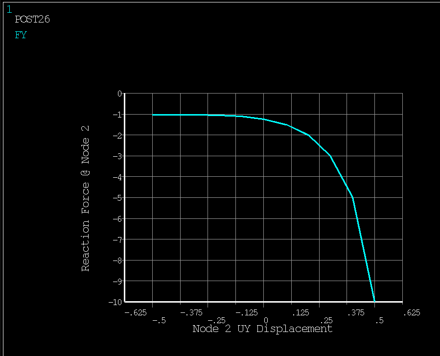
Note that as node 2 at the bottom of the two element model is moved upward, the reaction force becomes increasingly negative (the springs are pulling upward on node 2 with increasing force as node 2 gets closer to node 3).


In Mechanical, you would have to include commands like these in a command object, maybe written in such a way that the springs are attached to remote point nodes scoped to surfaces.


--Bill