Ansys Learning Forum › Forums › Discuss Simulation › General Mechanical › Support boundry condition for turbine blade subjected to thermal expansion › Reply To: Support boundry condition for turbine blade subjected to thermal expansion
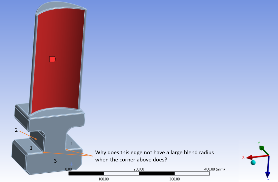
The faces numbered 1, 2, 3 identify faces you could use to create a “kinematic mount” that would allow for Free Expansion of the blade root under thermal expansion.
Assuming the two faces labelled 1 are parallel, use a compression only support to remove 3 DOF: Z, Rx and Ry. Apply a Remote Displacement, behavior = Deformable, on face 2 and remove 3 DOF: X, Y and Rz leaving the others Free. A different root design would have an angle between the two faces labelled 1 which would center the blade using the compression only support to remove 5 DOF and the Remote Displacement on face 3 would only need to set Y = 0.
A better simulation would model the matching features in the rotor and use frictional contact. Then the deformation in the rotor features would be included. The method of using just the blade and compression only support creates a perfectly rigid “rotor” with a sharp edge. Modeling the rotor allows you to put a blend on the edge of the features in the rotor.
 I expect to see high stress on the two corners the arrows point to because of the constraint forces on faces 1.
A remote displacement to apply a force to the face of the blade is not a good idea because more force will be applied near the center and less force will be applied far from the center if you are using a behavoir of Deformable. A better way to load the blade is with a pressure load. The best way to load the blade is to compute the pressure on the blade in a CFD simulation and import that load into Mechanical.


