Ansys Learning Forum › Forums › Discuss Simulation › General Mechanical › Solution seems to be different from the experimental results › Reply To: Solution seems to be different from the experimental results
Oh okay, I would use the actual data for the analysis, I gonna revert back to actual data. For the mesh is it okay for me to use 15 mm size, since I tried to use smaller mesh and my laptop doesn't have enough memory to run the analysis.
For the baseplate, unfortunately I didn't get much detailed information from my lecturer about the actual setup that has been done, because the experiment was done many years ago. I only managed to get some photo and video documentation that I would attach later on. But, my other lecturer said that it could be bolted onto the floor, so I gonna make some bolt holes in the baseplate. For the connection between the column, haunched on the bottom to the baseplate, my lecturer said that it is welded, can I model that as a bonded contact instead?
For the bolt, so you means that it is okay to model the bolt shank diameter by 12 mm, but the bolt hole in the column, beam, and gusset plate by 13 mm. For the contact is it correct to still apply the contact bodies with the bolt hole and the target bodies with the bolt shank although they doesn't make contact on the beginning of the analysis? For the bolt I just checked my archive, I got the photo of the bolt which I saw that the bolt is also using bolt ring, do I need to model the bolt ring also, and for the nut can I keep the bolt and the nut combined or do I need to split the body?
For the elements on the gusset I used just 1 segment through the thickness, I gonna change the mesh using sweep with 4 elements, is that the correct method to do the linear mesh? For the mesh method on the bolt holes you recommended, I haven't tried it yet, but I gonna do it later. Thankyou for the suggestion.
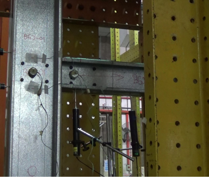
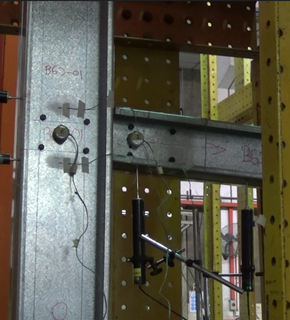
For the actual condition on the top of the column, I am not quite sure but on the picture I saw before, I could see that they are using some kind of lateral restraint on the Isolated Joint Test setup, I gonna give the picture as an attachment. But based on the condition, I could assume that it's just a frame used to hold the column so it doesnt move along with the beam.
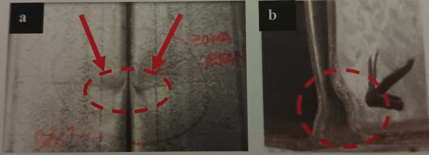
For the specimen condition after the experiment, the column does buckle a bit on the joint, the experimental test actually done 9 kinds of test, 3 beam to column with rectangular gusset plate, 3 with rectangular gusset plate with flange cleat, 3 with haunched gusset plate. I need to verify the rectangular and the haunched one, on the other experimental result I saw on the report, I could see also that some beam managed to penetrate the column a bit, leaving a dent on the column profile. For the eigenvalue buckling analysis you suggested, is it just the column I need to do analyze or the other part also like the baseplate, the bolt, the beam, the gusset plate?
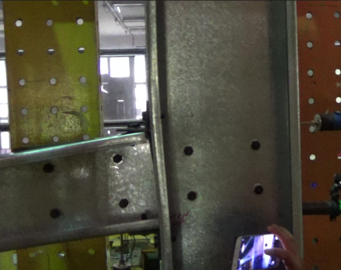
For the photograph of the experimental, I would attach some on the upcoming reply
This is the condition before testing
This is the condition after testing
This is the condition of the column and the beam
And this is the illustration of the IJT setup


