Ansys Learning Forum › Forums › Installation and Licensing › Ansys Products › Implement of constraints between two objects in frequency-domain calculations › Reply To: Implement of constraints between two objects in frequency-domain calculations
 Mike Pettit
Hi Tianyuan,
You should not expect the Connection Stiffness to change the added mass or radiation damping calculated by Aqwa. As you say, these are related to the forced vessel motion, but we do not care how much 'force' is required for that motion.
I don't think you need to worry about the spikes in the added mass/damping plots, as long as the heave terms are sensible. If you have constrained the structures in the time domain calculation, there will be no relative motion in surge/sway/roll/pitch, so there will be no radiation force in these directions.
I'm sorry that I didn't explain the Connection Stiffness definition well. To model the sliding connection between two structures in the Hydrodynamic Diffraction calculation, you should:
- add three Connection Stiffness objects under Connections
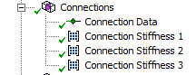
- for each Connection Stiffness, set the 'Connectivity' to 'Structure to Structure'

- set the 'Connected Structure A/B' as
Connected Structure A | Connected Structure B | |
Connection Stiffness 1 | Component1 | Component1 |
Connection Stiffness 2 | Component2 | Component2 |
Connection Stiffness 3 | Component1 | Component2 |
- for Connection Stiffness 1 and 2, set the stiffness values as e.g. K11 = K22 = 1e10 N/m; K44 = K55 = K66 = 1e12 N.m/deg (leave K33 as zero to allow relative heave motion)
- for Connection Stiffness 3, set the stiffness values as e.g. K11 = K22 = -1e10 N/m; K44 = K55 = K66 = -1e12 N.m/deg (leave K33 as zero to allow relative heave motion)
Mike


