Ansys Learning Forum › Forums › Discuss Simulation › 3D Design › Creation of Periodic B.C in ICEM › Reply To: Creation of Periodic B.C in ICEM
 mjmiddle
The negative or positive value does not matter. You can use either 0 0 -0.2 or 0 0 0.2.
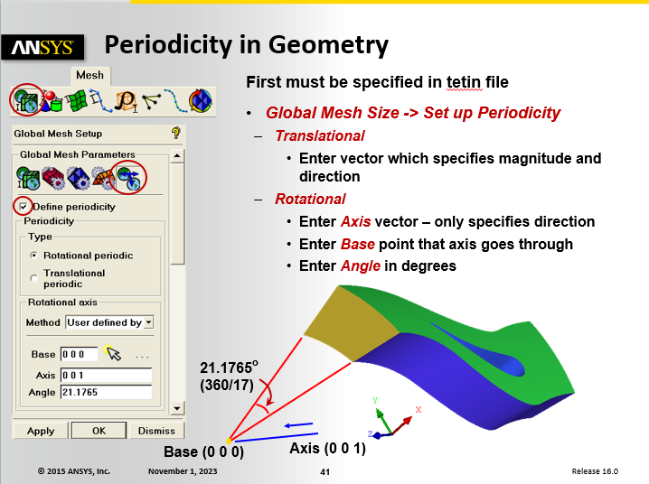
It just defines a distance when node locations will be linked to be the same values in the directions normal to this vector and matching in vector length distance along the vector. After setting up the periodicity direction in the global settings, you must still link the block vertices. This is shown in the ICEM CFD training. Two lectures slides are shown below. The example shows angular periodicity, but the procedure is the same for linear periodicity:
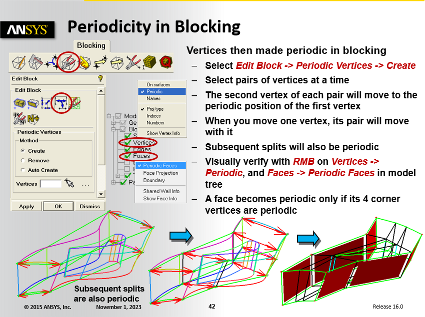
You will need to design your blocking scheme so that the face structure matches at the periodic faces.


