Ansys Learning Forum › Forums › Discuss Simulation › General Mechanical › PCB trace mapping issue › Reply To: PCB trace mapping issue
 umesh_maheshwari
Hello All
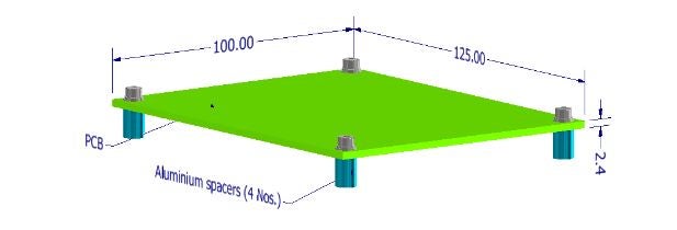
My PCB (made of FR4 having 12 layer with total thickness of 2.4 mm) geometry has 4 nos. of diameter 3.5 mm from 5 mm inside from edges and assembled using M3.5 socket head screws. PCB is mounted on vibration plate through Diameter 7 aluminium spaces at 4 mounting location which also have diameter 3.5 through holes. Each screw is given torque of 58 N-cm.
I am facing issue after trace mapping on 2d shell geometry. When i am not considering the hole in FE analysis and fixed support is taken at center node at hole location , my simulation first mode frequency is matching with that of actual vibration result but when i am considering the hole and hole edge is given as fixed boundary condition , my simulation first mode frequency is higher than the vibration result.
Anyone can help in this regards , i am not able to understand why such a thing is happening.
