Ansys Learning Forum › Forums › Discuss Simulation › Electronics › Maxwell circuit giving wrong simulation results › Reply To: Maxwell circuit giving wrong simulation results
 joao.pranke
Of course!
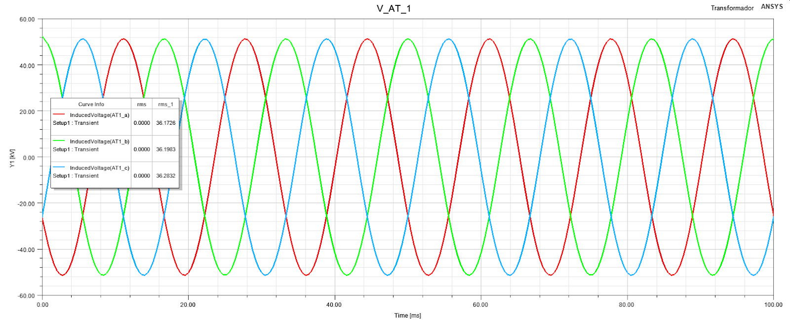
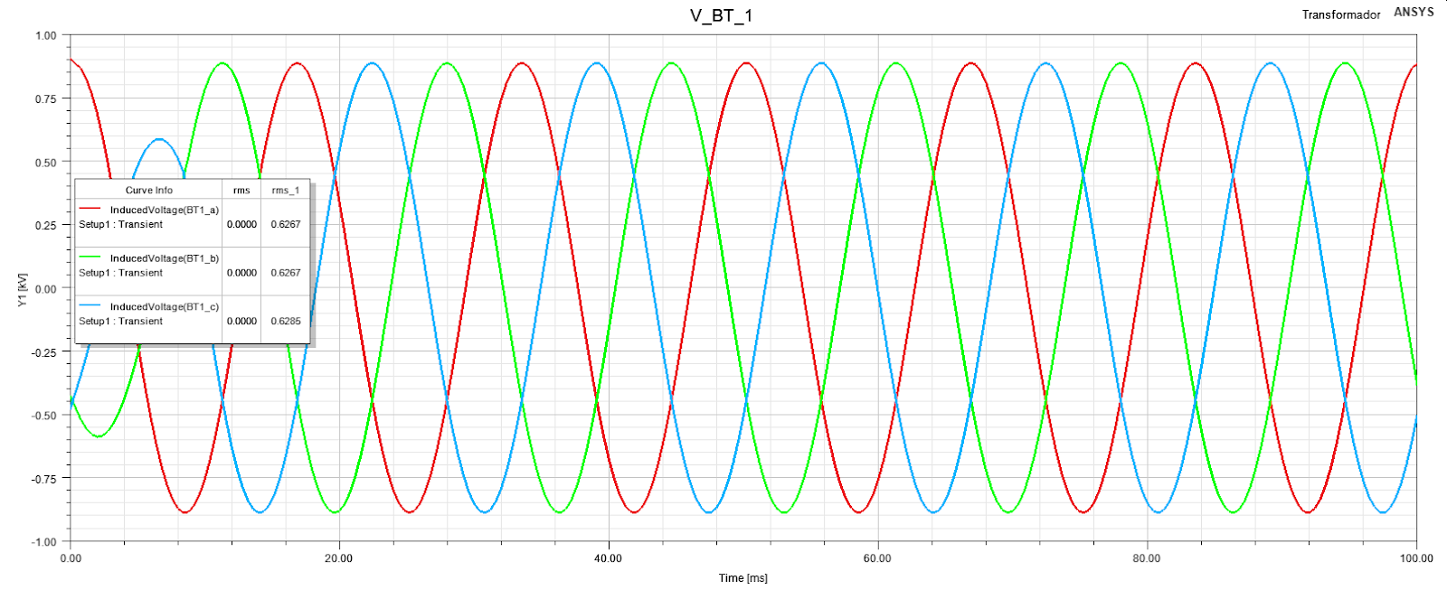
The line voltage is 36.225 kV;
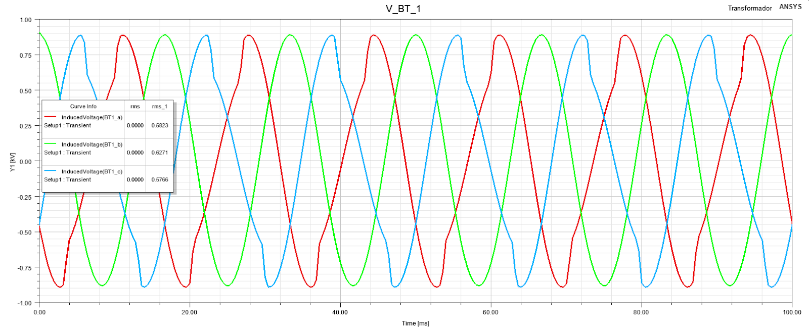
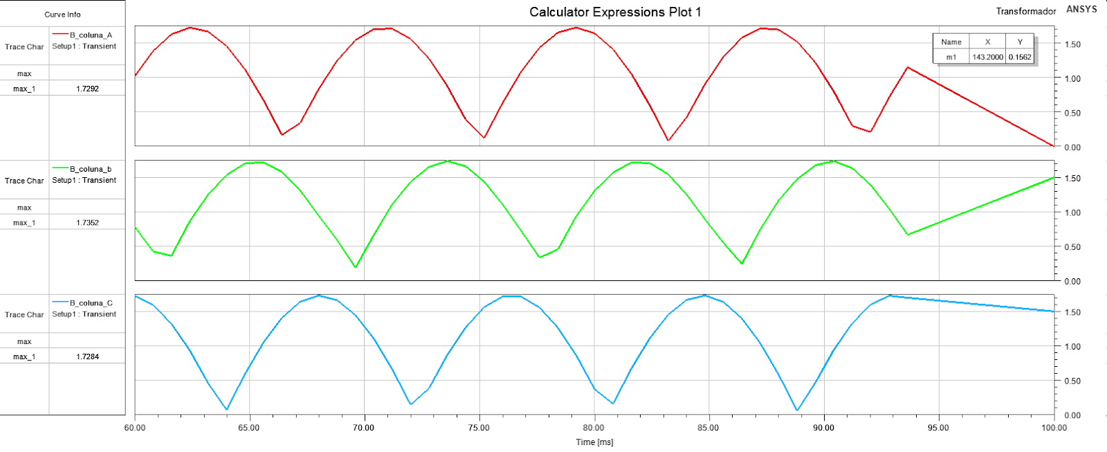
With the external circuit:
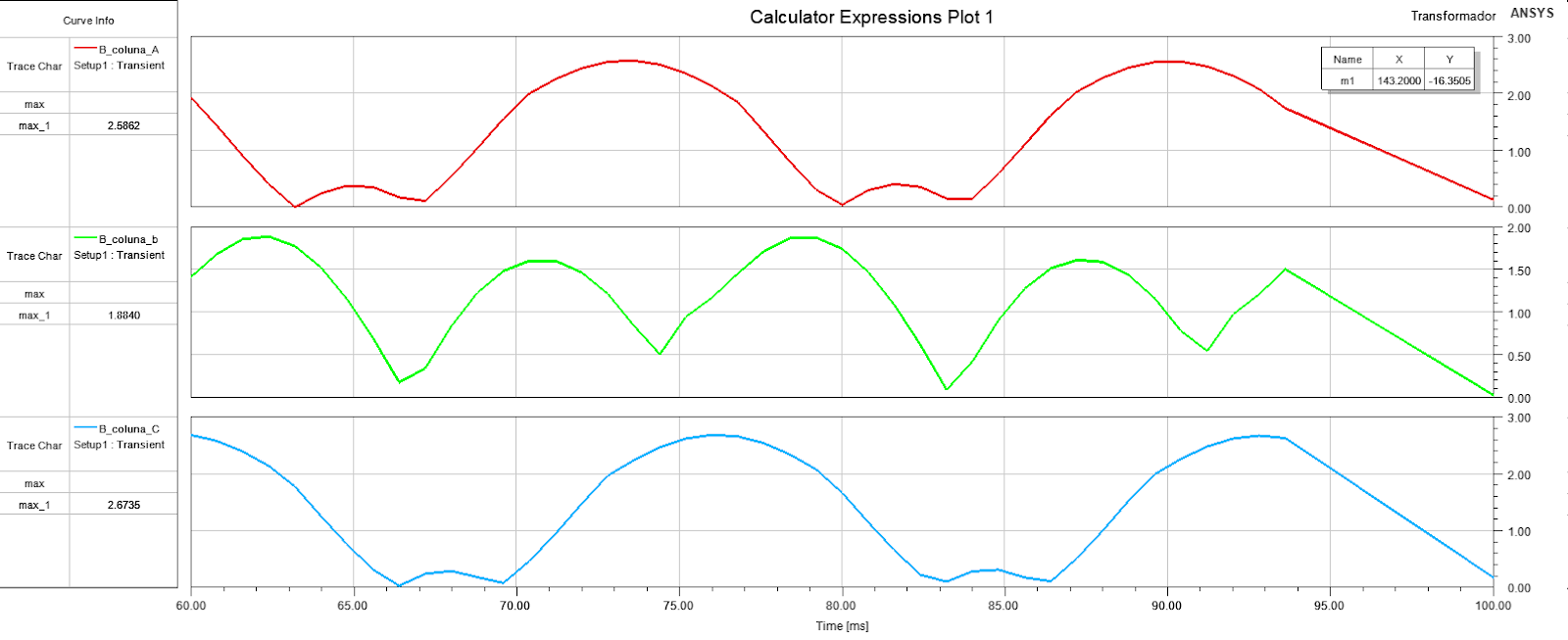
(This last graph is the max amplitude of the flux density B on sections of core legs)
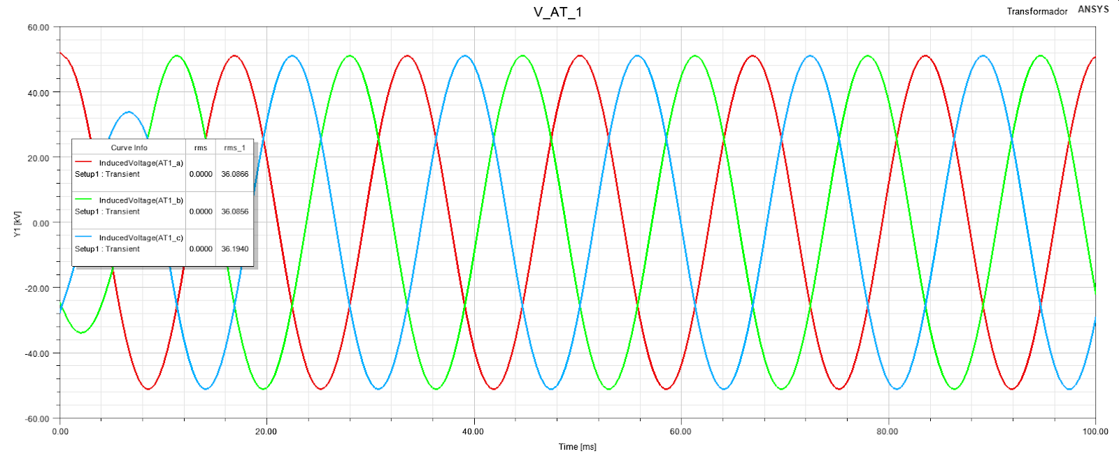
Without the external circuit:
The excitation on the widings is the following (AT1 and AT2 are in parallel):
AT1_a=36225*sqrt(2)*cos(2*pi*60*time)
AT1_b=36225*sqrt(2)*cos(2*pi*60*time+120deg)
AT1_c=36225*sqrt(2)*cos(2*pi*60*time+240deg)
AT2_a=36225*sqrt(2)*cos(2*pi*60*time)
AT2_b=36225*sqrt(2)*cos(2*pi*60*time+120deg)
AT2_c=36225*sqrt(2)*cos(2*pi*60*time+240deg)
Here the flux density is almost exactly of the project (1,73 T)
As i can see, the excitation is exactly the same with or without the external circuit, but the simulation does't work with the circuit.


