Ansys Learning Forum › Forums › Discuss Simulation › General Mechanical › Modelling contact between reinforcement pad and shell/nozzle › Reply To: Modelling contact between reinforcement pad and shell/nozzle
 tortju
Thank you for your thorough reply!
I simplified the model a bit (merging the already splitted bodies) such that the model now consisted of only three solids: the shell, the nozzle and the reinforcement pad.
After doing this I followed your suggestion of copying and pasting the outer surfaces of the shell and the nozzle and the bottom surface of the reinforcement pad. I rejected sharing the surfaces and I got the two coincident surfaces (no need for manual projection). I got the following result in SpaceClaim:
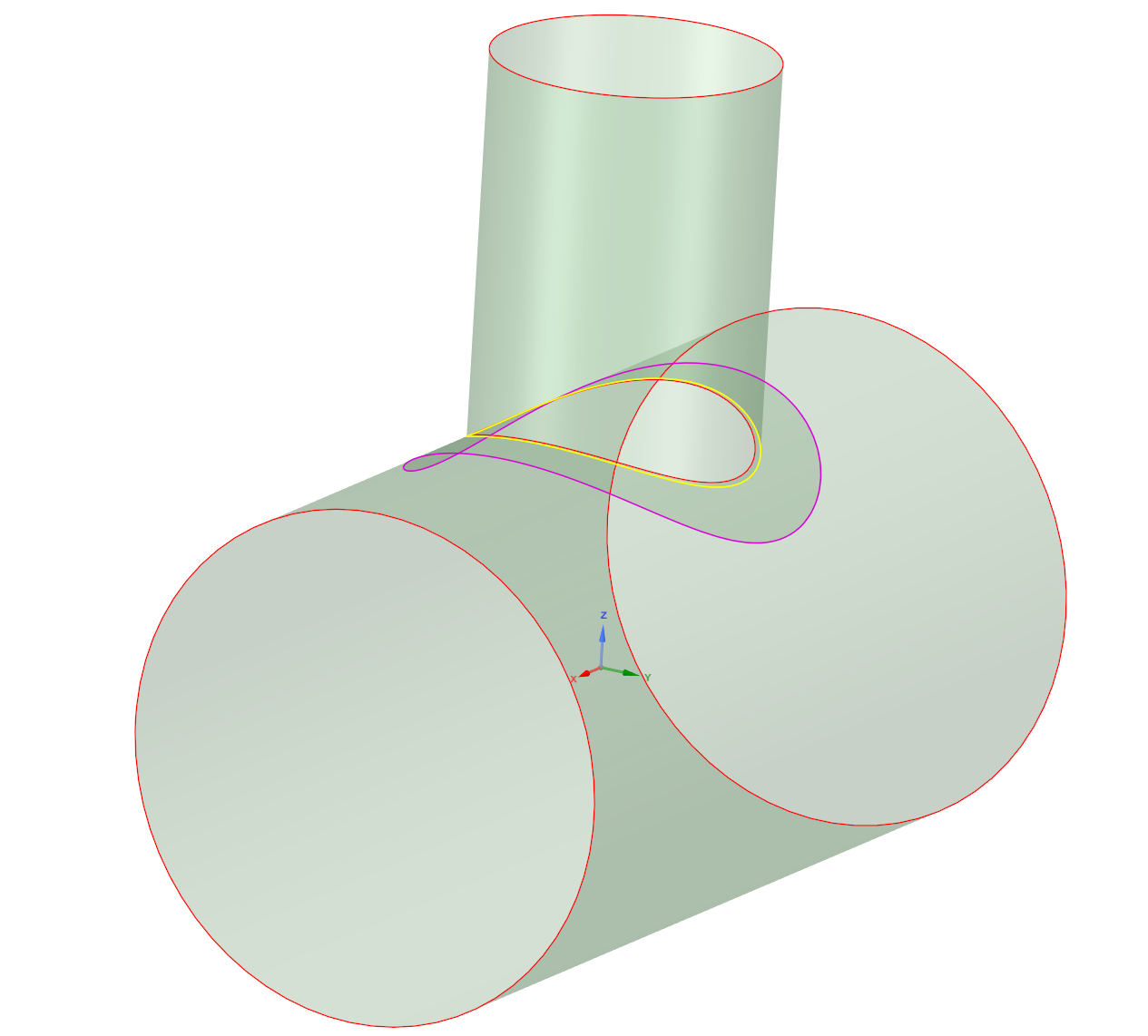
The different colors indicate how many edges/surfaces each edge are connected to, right?
I followed your directions in Mechanical as well. The program suggested bonded contact between the bottom face of the reinforcement pad and the top face of the shell, but I suppressed this (no contacts used in the model). This appeared to work fine, but I noticed a gap appearing between the reinforcement pad and the nozzle on two opposite sides:
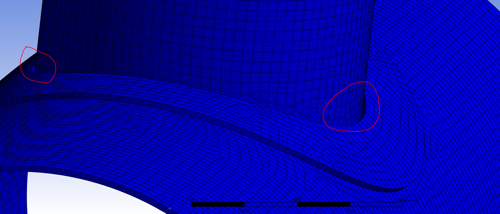
This doesn't appear to be any problem on the two other sides:

This may only be some kind of bad geometry visualisation, but I don't think so since this gap causes large stress concentrations in the equivalent stress results:
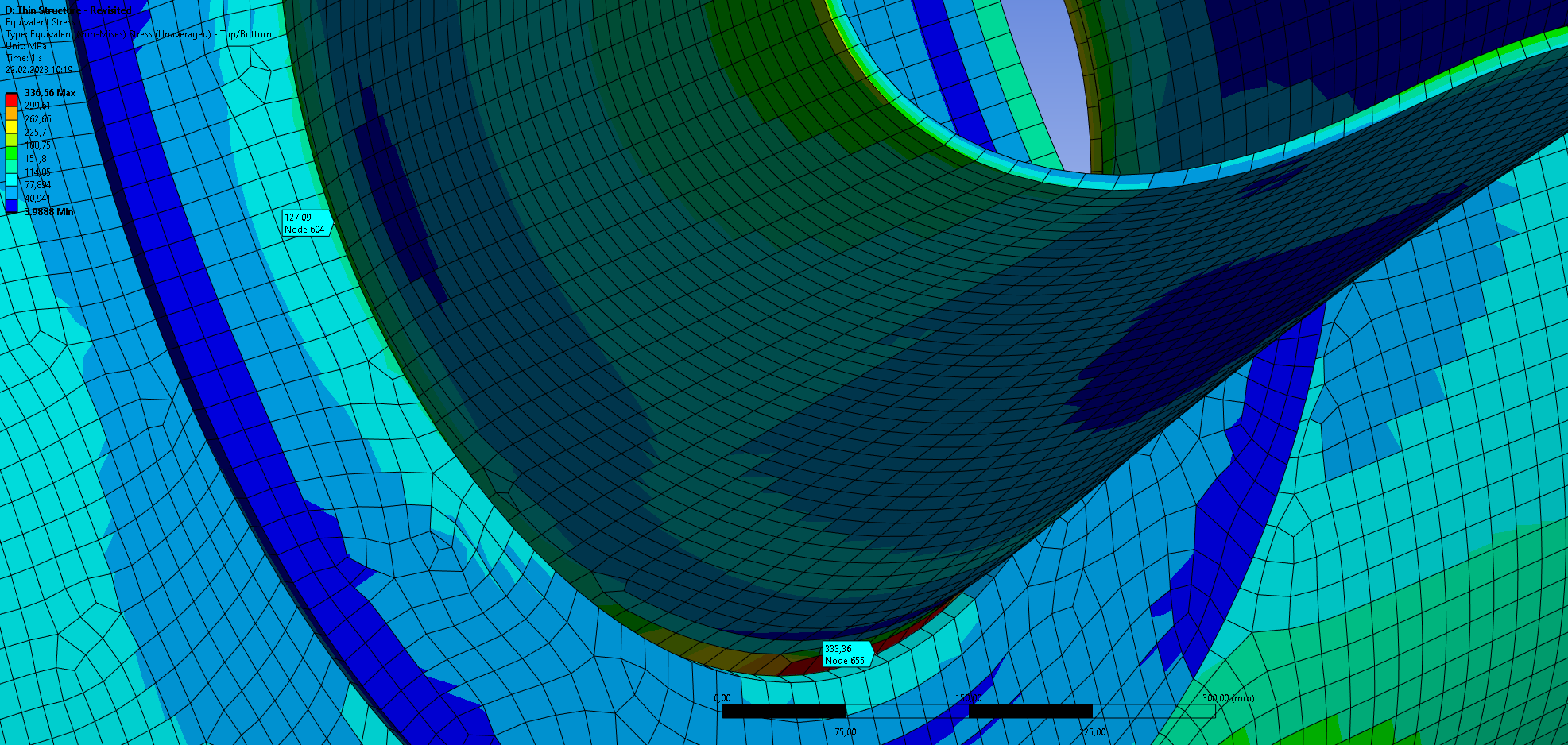
Do you have any suggestions on what may be the problem here? The edges seem to be shared correctly and the elements are nicely aligned over the connected edges.


