Ansys Learning Forum › Forums › Discuss Simulation › General Mechanical › Modelling contact between reinforcement pad and shell/nozzle › Reply To: Modelling contact between reinforcement pad and shell/nozzle
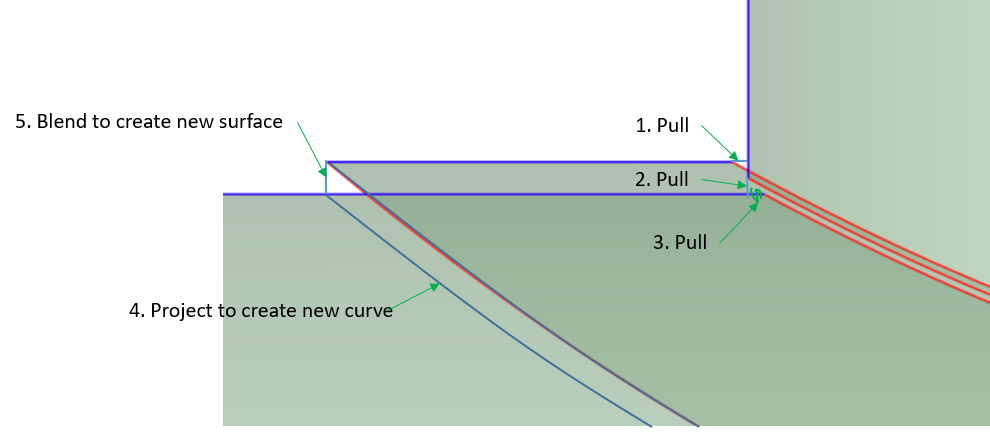
If you follow the directions given, material is created to reach the midsurface.
An equivalent model that would have similar results woud be to do step 4 above, and to project the edge of the pad onto the nozzle to create the edge that step 1 above creates. Then use edge-to-edge bonded contact to jump the gaps. In either case, the connection is made at the midsurface.
A better model is to copy/paste the outer surfaces of the shell and nozzle and the bottom surface of the pad. Now all the surfaces have edges that touch so there is no need to create a new surface, there are no gaps to close. In SpaceClaim when you click the Share button, you must reject sharing the surfaces and only share the edges so the pad does not merge with the shell. This may create the projection of the outer curve of the pad onto the shell. If not, do that manually. At the end, you need two coincident surfaces, one for the pad and one for the shell.
Then in Mechanical, since these surfaces are not midsurfaces, you must type in the 12 mm thickness manually, and you also select the offset to be Top or Bottom appropriately. After you mesh, turn on Shell Thickness and you can check that the offest has been correctly defined as it should look like the solid model.


