Ansys Learning Forum › Forums › Discuss Simulation › General Mechanical › Constraint a point / coordinate › Reply To: Constraint a point / coordinate
March 27, 2022 at 1:40 pm
 peteroznewman
Subscriber
I do share my knowledge on a YouTube channel. https://www.youtube.com/channel/UC0cffQ4Ccz5MA6LefcdBPZg/videos That is where I store the videos I use to answer questions on this forum. When the forum was converted to a new platform, some of my best discussions were lost. Fortunately, I can still help students who ask the same question by pointing them to a video, even though the link to the old discussion is broken. My most popular video has nearly 20k views, but the discussion it supported was lost over a year ago.
Q11. For a Remote Displacement scoped to both the top and bottom holes, there will be a pilot node at the center of the frame, between the two holes. The nodes around the top hole will move approximately as a group while the nodes around the bottom hole will move approximately as a separate group. Now if the top group rotates 2 degrees about Y, while the bottom group rotates -2 degrees about Y, the average rotation of all the nodes is 0. That is what the Remote Displacement is enforcing.
Q22. When you create a Remote Displacement (or Force), a Remote Point is automatically created under-the-hood. You can expose visibility to that by right click on the Remote Displacement and select Promote to Remote Point. You would do this if you wanted to reuse the Remote point, such as to apply a force as well as the displacement that you wanted. By default, a Remote object will use the Global coordinate system but you can specify any Cartesian coordinate system you create to control the loads or supports at the pilot node.
Q33. The location of the Remote Point/Pilot Node (whether under-the-hood or manually) is created at the centroid of the scoped geometry and listed in Global Coordinates. If you change the Coordinate System, the location X, Y, Z values DO NOT CHANGE to keep the point at the same location in space. I wish it would as I expect many people assume it would do that. You have to be very careful when changing the Coordinate System for a Remote Point to update the X, Y, Z values of the location to be exactly what you want. See the example in Q44. Another way to get unexpected locations in a Remote object is if you have created a first object, say for the top hole, and then you use Duplicate on the object in the Outline and scope the second duplicated object to the bottom hole. When you rescope an existing Remote object to new geometry, the location field DOES NOT UPDATE. That is why I never duplicate Remote objects in the Outline. I always create each one independently so that each one has the pilot node at the centroid of the scoped geometry.
Q44. The location of the Remote Point (whether under-the-hood or manually) is created at the centroid of the scoped geometry. You can adjust the coordinates by typing in new values. An example of when you would want to move the default location is when you have a long cantilever beam with a tip force. The cantilever has been split into two pieces: the tip and the base. There is a coordinate system at the tip, but the tip body is suppressed. The load enters at the split face where the remote point was created but you want the Force at the tip, so you change to the coordinate system at the tip then type 0,0,0 for the location. Now the force at the tip will be converted to a set of nodal forces that create the force and bending moment at the split plane. You don't need another coordinate system if you know the global coordinates for the location of the tip force. In your case, you don't need a special coordinate system.
Q55. If you use two Remote Displacements and each one has a pilot node at the center of each hole, you will enforce that the top group of nodes has an average rotation of 0, not the 2 degrees you got in Q11 and the bottom group of nodes will have an average rotation of 0 degrees, not the -2 degrees you got in Q11. So the stress results will be different. The setup of Q11 is more similar to no remote displacement, which allows each group of nodes to rotate, but in equal and opposite amounts.
Q66. You must split the geometry in CAD or SC before you bring it in to apply a Symmetry Region.
Q77. Once you observe that the maximum stress is on one face of the model, you can add a Von Mises Equivalent Stress output and scope it to that face. On the Details window for that output is a Results category and a square next to the Maximum value. Click that square and you will get a P for Parameter. The Workbench schematic will now have a Parameter Set box with an Output. Insert a Sizing Mesh Control on that face with a specified element size of 5 mm. Click the square to get a P for the element size. The Parameter Set box will now have an Input. In Workbench, open the Parameter Set box and type a series of smaller and smaller values in the Element Size column in the Table of Design Points. The best practice is to use a fixed ratio for the size where the ratio is between 1.2 and 2. It looks like an element size of 5 mm puts 2 elements across the thickness of the frame so using a ratio of 1.5, in the Table of Design Points, type in the seven rows below for the element size.
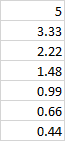 Click the Update All Design Points button and go away for a break. Workbench will automatically solve the model seven times and fill out the Maximum Stress in the output column. Copy the table and plot the values in Excel. If the stress value is converging on a fixed value as the element size tends toward zero, then you have your True Stress result. If the stress value keeps increasing, then this face includes a singularity and the geometry will need to be refined to get rid of that.
Regards, Peter
Q11. For a Remote Displacement scoped to both the top and bottom holes, there will be a pilot node at the center of the frame, between the two holes. The nodes around the top hole will move approximately as a group while the nodes around the bottom hole will move approximately as a separate group. Now if the top group rotates 2 degrees about Y, while the bottom group rotates -2 degrees about Y, the average rotation of all the nodes is 0. That is what the Remote Displacement is enforcing.
Q22. When you create a Remote Displacement (or Force), a Remote Point is automatically created under-the-hood. You can expose visibility to that by right click on the Remote Displacement and select Promote to Remote Point. You would do this if you wanted to reuse the Remote point, such as to apply a force as well as the displacement that you wanted. By default, a Remote object will use the Global coordinate system but you can specify any Cartesian coordinate system you create to control the loads or supports at the pilot node.
Q33. The location of the Remote Point/Pilot Node (whether under-the-hood or manually) is created at the centroid of the scoped geometry and listed in Global Coordinates. If you change the Coordinate System, the location X, Y, Z values DO NOT CHANGE to keep the point at the same location in space. I wish it would as I expect many people assume it would do that. You have to be very careful when changing the Coordinate System for a Remote Point to update the X, Y, Z values of the location to be exactly what you want. See the example in Q44. Another way to get unexpected locations in a Remote object is if you have created a first object, say for the top hole, and then you use Duplicate on the object in the Outline and scope the second duplicated object to the bottom hole. When you rescope an existing Remote object to new geometry, the location field DOES NOT UPDATE. That is why I never duplicate Remote objects in the Outline. I always create each one independently so that each one has the pilot node at the centroid of the scoped geometry.
Q44. The location of the Remote Point (whether under-the-hood or manually) is created at the centroid of the scoped geometry. You can adjust the coordinates by typing in new values. An example of when you would want to move the default location is when you have a long cantilever beam with a tip force. The cantilever has been split into two pieces: the tip and the base. There is a coordinate system at the tip, but the tip body is suppressed. The load enters at the split face where the remote point was created but you want the Force at the tip, so you change to the coordinate system at the tip then type 0,0,0 for the location. Now the force at the tip will be converted to a set of nodal forces that create the force and bending moment at the split plane. You don't need another coordinate system if you know the global coordinates for the location of the tip force. In your case, you don't need a special coordinate system.
Q55. If you use two Remote Displacements and each one has a pilot node at the center of each hole, you will enforce that the top group of nodes has an average rotation of 0, not the 2 degrees you got in Q11 and the bottom group of nodes will have an average rotation of 0 degrees, not the -2 degrees you got in Q11. So the stress results will be different. The setup of Q11 is more similar to no remote displacement, which allows each group of nodes to rotate, but in equal and opposite amounts.
Q66. You must split the geometry in CAD or SC before you bring it in to apply a Symmetry Region.
Q77. Once you observe that the maximum stress is on one face of the model, you can add a Von Mises Equivalent Stress output and scope it to that face. On the Details window for that output is a Results category and a square next to the Maximum value. Click that square and you will get a P for Parameter. The Workbench schematic will now have a Parameter Set box with an Output. Insert a Sizing Mesh Control on that face with a specified element size of 5 mm. Click the square to get a P for the element size. The Parameter Set box will now have an Input. In Workbench, open the Parameter Set box and type a series of smaller and smaller values in the Element Size column in the Table of Design Points. The best practice is to use a fixed ratio for the size where the ratio is between 1.2 and 2. It looks like an element size of 5 mm puts 2 elements across the thickness of the frame so using a ratio of 1.5, in the Table of Design Points, type in the seven rows below for the element size.
Click the Update All Design Points button and go away for a break. Workbench will automatically solve the model seven times and fill out the Maximum Stress in the output column. Copy the table and plot the values in Excel. If the stress value is converging on a fixed value as the element size tends toward zero, then you have your True Stress result. If the stress value keeps increasing, then this face includes a singularity and the geometry will need to be refined to get rid of that.Regards, Peter


