Ansys Learning Forum › Forums › Discuss Simulation › General Mechanical › Why am I seeing Residual Forces so huge here? › Reply To: Why am I seeing Residual Forces so huge here?
December 26, 2021 at 6:35 pm
Subscriber
That's a great video. Ansys is frequently adding functionality that makes it faster and easier to take geometry and get a result with a minimum amount of effort. I learned to make contact models before Contact Stabilization was available in Mechanical, so I had to move parts in CAD prior to starting the model to get closed contact status. That works when the load is in one direction only, but doubles the work when the load reverses. Contact stabilization could potentially allow load in both directions to solve with no intervention.
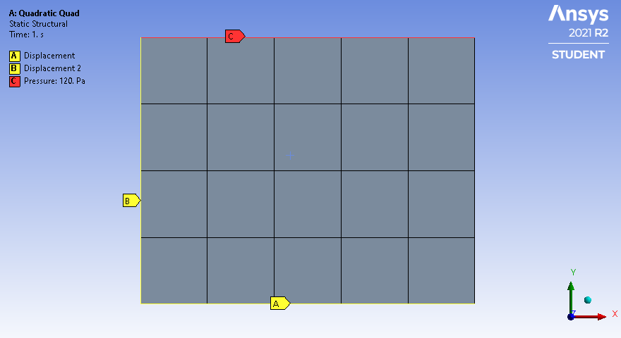
I wanted to add another reason for "hot spots" in the NR residual force plot, which is the way a uniform pressure is resolved into nodal forces on quadratic elements. In the example below, a uniform pressure load of 120 Pa is on the top, a displacement of Y=0 is on the bottom of the square, and X=0 on the left edge.
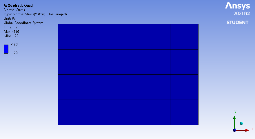
 The element result is a uniform stress in the part. The reaction force on the bottom edge is 6 N. Note that along the bottom edge, there are three middle elements and two side elements.
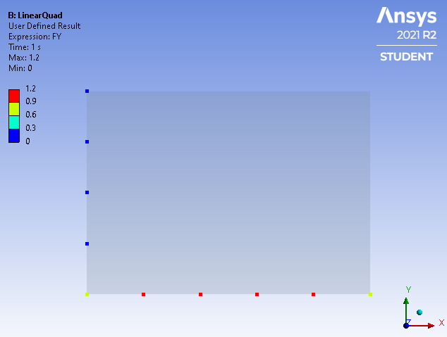
 For Linear elements, the nodal forces on the 4 nodes of the three middle elements is 1.2 N, while the corner nodes on the side elements have 0.6 N. It makes sense that the corner nodes on the side elements have half the nodal force since if another column of elements were added to that side, that node would be attached to two middle elements and the total nodal force would come up to the 1.2 N value expected on middle element nodes.
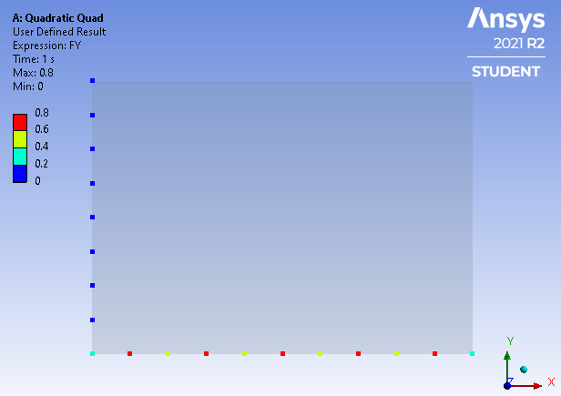
 For Quadratic elements, each element has a midside node and a corner node. The nodal force on the midside nodes of the three middle elements is 0.8N while the corner node on those middle elements is only 0.4 N. This means that for a uniform pressure, the nodal force oscillates high-low across each element face by a factor of 2:1 which is very different to the Linear elements where the nodal forces are constant across the middle elements. Similar to the Linear case, the side elements have corner nodes half that of a middle node at 0.2 N.
 The above examples are for 2D elements, but the effect is even larger on 3D elements. See this reference:
http://rickbradford.co.uk/NodalForcesEquivalenttoPressure.pdf where the ratio in the middle of the face is 2:-1 which means the element corner nodal force is in the opposite direction to the pressure! See that the nodal force oscillates between -0.4 N and 0.8 N on the bottom face.
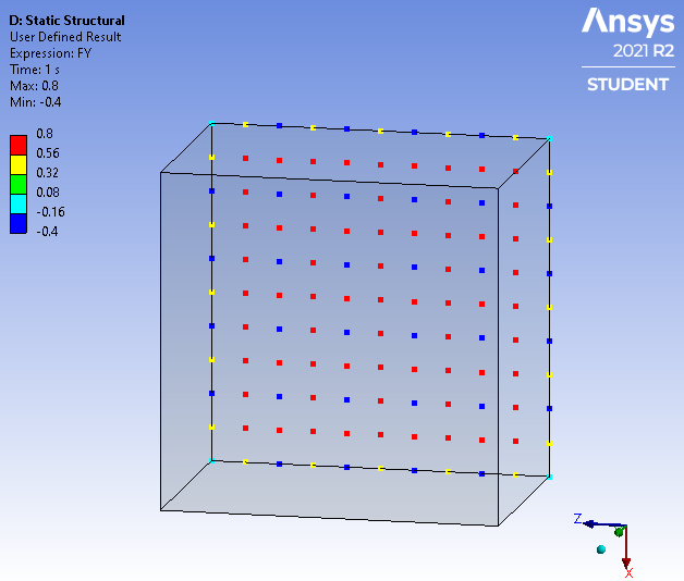 This same effect happens during contact. If the contact result is supposed to be a uniform pressure, the nodal forces are going to oscillate if you have quadratic elements. This is why in challenging contact problems, linear elements sometimes help, but due to the reduction in the ability to represent stress gradients, the element size should be cut at least in half to maintain the total number of nodes on the surface.
The problem is linear tetrahedral elements are to be avoided always because they are overly stiff, while linear hex elements are acceptable. However, it is a lot more work to create hex elements on complex geometry. A significant problem with linear elements is on cylindrical faces because linear elements have straight edges. Contrast that with quadratic elements that have curved edges. This means that if the nodes on the ID of the hole don't line up with the nodes on the OD of the post, but land in the middle of the element face, then there can be a significant deviation from the cylindrical surface.
I wanted to add another reason for "hot spots" in the NR residual force plot, which is the way a uniform pressure is resolved into nodal forces on quadratic elements. In the example below, a uniform pressure load of 120 Pa is on the top, a displacement of Y=0 is on the bottom of the square, and X=0 on the left edge.
 The element result is a uniform stress in the part. The reaction force on the bottom edge is 6 N. Note that along the bottom edge, there are three middle elements and two side elements.
 For Linear elements, the nodal forces on the 4 nodes of the three middle elements is 1.2 N, while the corner nodes on the side elements have 0.6 N. It makes sense that the corner nodes on the side elements have half the nodal force since if another column of elements were added to that side, that node would be attached to two middle elements and the total nodal force would come up to the 1.2 N value expected on middle element nodes.
 For Quadratic elements, each element has a midside node and a corner node. The nodal force on the midside nodes of the three middle elements is 0.8N while the corner node on those middle elements is only 0.4 N. This means that for a uniform pressure, the nodal force oscillates high-low across each element face by a factor of 2:1 which is very different to the Linear elements where the nodal forces are constant across the middle elements. Similar to the Linear case, the side elements have corner nodes half that of a middle node at 0.2 N.
 The above examples are for 2D elements, but the effect is even larger on 3D elements. See this reference:
http://rickbradford.co.uk/NodalForcesEquivalenttoPressure.pdf where the ratio in the middle of the face is 2:-1 which means the element corner nodal force is in the opposite direction to the pressure! See that the nodal force oscillates between -0.4 N and 0.8 N on the bottom face.
 This same effect happens during contact. If the contact result is supposed to be a uniform pressure, the nodal forces are going to oscillate if you have quadratic elements. This is why in challenging contact problems, linear elements sometimes help, but due to the reduction in the ability to represent stress gradients, the element size should be cut at least in half to maintain the total number of nodes on the surface.
 The problem is linear tetrahedral elements are to be avoided always because they are overly stiff, while linear hex elements are acceptable. However, it is a lot more work to create hex elements on complex geometry. A significant problem with linear elements is on cylindrical faces because linear elements have straight edges. Contrast that with quadratic elements that have curved edges. This means that if the nodes on the ID of the hole don't line up with the nodes on the OD of the post, but land in the middle of the element face, then there can be a significant deviation from the cylindrical surface.


