Ansys Learning Forum › Forums › Discuss Simulation › General Mechanical › Weird strain spikes in a cylinder with varying thickness › Reply To: Weird strain spikes in a cylinder with varying thickness
October 30, 2021 at 5:34 am
Ansys Employee
Hi @adityap
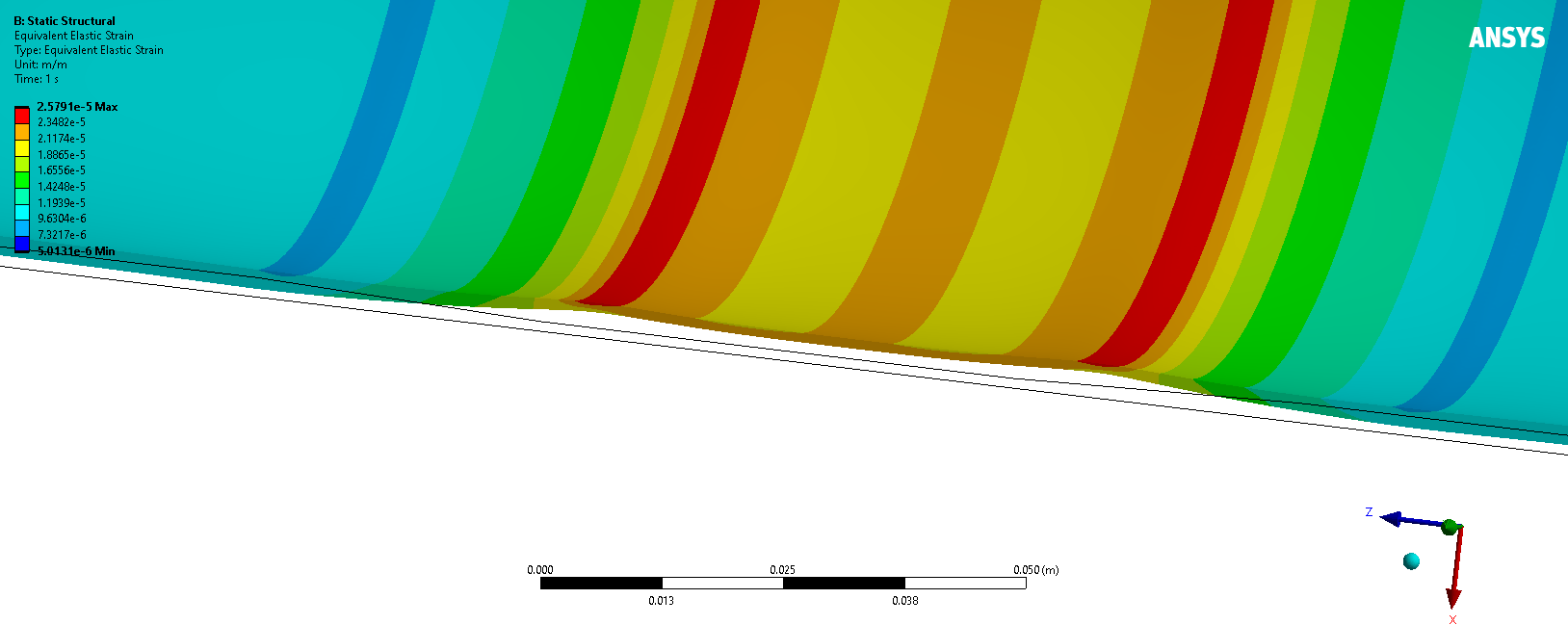
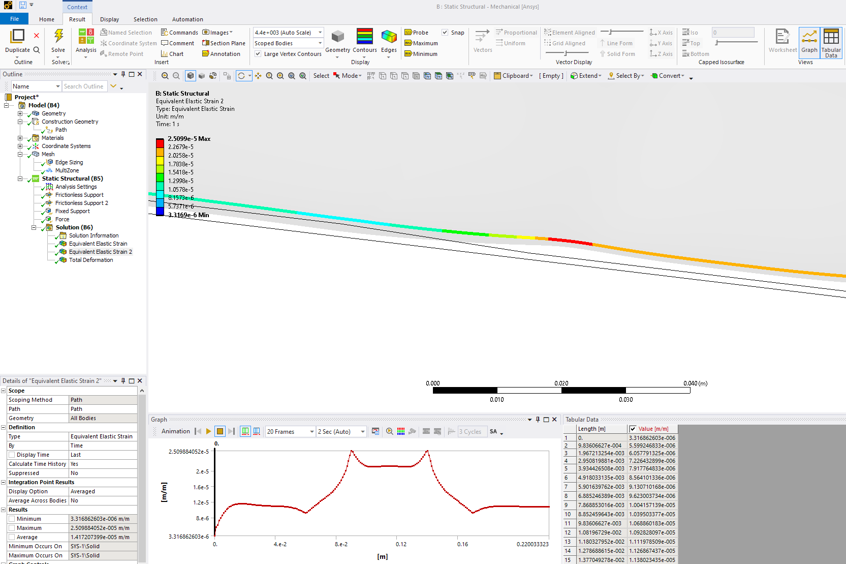
So, now that I Iook in more detail, these spikes are expected. If you just take and put the tube in tension you will see this behavior Why?


If you were to do a free body diagram at the transition, you have what is below. The line of action of the force of the two sections has an offset. This results in a local moment being generated, and we can see that in the tube as it bends. Another way to think about it is to imagine the below is a a cross section flat slice of material with a taper. When we pull on the two ends, the specimen will try to rotate to establish equilibrium, and if it could rotate freely, the moment would be eliminated as the force vectors would align. But the structure can not simply rotate as if pinned , instead it has to elastically deform, and hence we end up with the development of an internal moment, and resulting stress peaks.
 I have seen this in practice in several occasions in my engineering practice.
A large thin wall tube with an indent (imagine you bang a tube with a hammer and dent it. Ignore any plastic deformation, pull on the tube and you will see local stress concentrations due to local bending. I have seen this proven with Ansys and small strain gauges. Some engineers at the time had a hard time believing the stress concentration was as high as we predicted with FEA, but then we go exact match with strain gauges.
Also, single overlap shear test specimens used in adhesive testing have the same offset effect and generate large moments that develop peel stress in the adhesive.
What you are seeing is not related to element behavior, but rather physical. Now with that said, you may see slight differences based on the formulation, and number of elements (mesh convergences) but do not expect to eliminate the spikes. Fundamental physics indicates they should be there. I hope this helps.
Regards Sean


If you were to do a free body diagram at the transition, you have what is below. The line of action of the force of the two sections has an offset. This results in a local moment being generated, and we can see that in the tube as it bends. Another way to think about it is to imagine the below is a a cross section flat slice of material with a taper. When we pull on the two ends, the specimen will try to rotate to establish equilibrium, and if it could rotate freely, the moment would be eliminated as the force vectors would align. But the structure can not simply rotate as if pinned , instead it has to elastically deform, and hence we end up with the development of an internal moment, and resulting stress peaks.
 I have seen this in practice in several occasions in my engineering practice.
 A large thin wall tube with an indent (imagine you bang a tube with a hammer and dent it. Ignore any plastic deformation, pull on the tube and you will see local stress concentrations due to local bending. I have seen this proven with Ansys and small strain gauges. Some engineers at the time had a hard time believing the stress concentration was as high as we predicted with FEA, but then we go exact match with strain gauges.
Also, single overlap shear test specimens used in adhesive testing have the same offset effect and generate large moments that develop peel stress in the adhesive.
What you are seeing is not related to element behavior, but rather physical. Now with that said, you may see slight differences based on the formulation, and number of elements (mesh convergences) but do not expect to eliminate the spikes. Fundamental physics indicates they should be there. I hope this helps.
Regards Sean


