Ansys Learning Forum › Forums › Discuss Simulation › Electronics › Ansys Sherlock Constraints › Reply To: Ansys Sherlock Constraints
October 26, 2021 at 12:20 pm
Subscriber
Hi David
Thank you for your response -
The area of most interest to me was thermal cycling (manifesting as mechanical stress on components with different CTE's).
I aim to build a thermal profile using AEDT to serve as an input for sherlock. This would generate the expected service temperatures at low and high load operating points for the PCB.
The output of this (I was hoping) would be a reliability score based on the thermal load profile, which I could test and validate (ie cycle the PCB til failure and compare predicted cycles against real cycles)
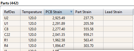
From Studying the theory documentation, it appears it looks at the temperature delta in the thermal profile, and computes based off this and the ECAD data/component library. It looks in 2021 R2 that a reliability score has been withdrawn when looking just at therm/mechanical loading - the documentation suggests the user can interpret the strain output for further reliability studies.
Do you have any suggestions on how to proceed? I am keen to keep the scope to just thermal cycling on the PCB, and really require a means of modelling predicted cycles to failure. At a stab, I presume I could look at the reported strain from each component in sherlock, assume bulk material properties at each interface, and put on a SN curve and indicate cycles til failure that way?


(the component data is taken from the example ODB++ -)
Kind Regards
Toby
Thank you for your response -
The area of most interest to me was thermal cycling (manifesting as mechanical stress on components with different CTE's).
I aim to build a thermal profile using AEDT to serve as an input for sherlock. This would generate the expected service temperatures at low and high load operating points for the PCB.
The output of this (I was hoping) would be a reliability score based on the thermal load profile, which I could test and validate (ie cycle the PCB til failure and compare predicted cycles against real cycles)
From Studying the theory documentation, it appears it looks at the temperature delta in the thermal profile, and computes based off this and the ECAD data/component library. It looks in 2021 R2 that a reliability score has been withdrawn when looking just at therm/mechanical loading - the documentation suggests the user can interpret the strain output for further reliability studies.
Do you have any suggestions on how to proceed? I am keen to keep the scope to just thermal cycling on the PCB, and really require a means of modelling predicted cycles to failure. At a stab, I presume I could look at the reported strain from each component in sherlock, assume bulk material properties at each interface, and put on a SN curve and indicate cycles til failure that way?


(the component data is taken from the example ODB++ -)
Kind Regards
Toby


