Ansys Learning Forum › Forums › Discuss Simulation › Electronics › Push Excitations not working in dynamic link › Reply To: Push Excitations not working in dynamic link
September 2, 2021 at 6:34 am
Subscriber
Hello
unfortunately that is not the case. I followed multiple courses and guides on the dynamic link feature in ANSYS HFSS. But in contrast to their solution mine looks like this:
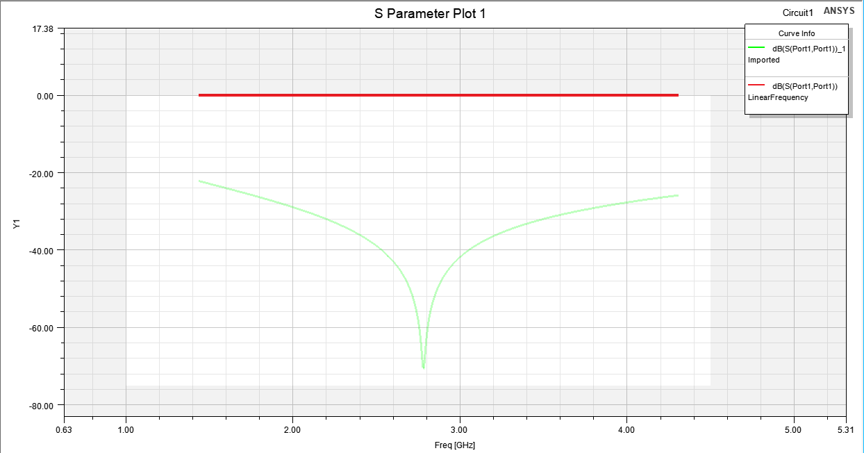
 This is the circuit simulation. As one can see the unmatched red curve and the green curve after applying the matching network. The circuit simulation displays the desired result and confirms the matching should work.
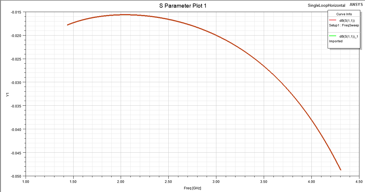
Now the same plot before and after pushing excitations in HFSS:
 The red (before) and green (after) curves overlap because the matching network excitation was NOT applied to HFSS even tho the software says the excitation push was successful. I'm really confused since the matching apparently worked, according to ANSYS Circuits.
The Model is a DrivenModal Solution (tried with Terminal Solution as well - same result) with one lumped port as excitation.
I'm at my wits end to be honest.
BR
Swoopoo
 This is the circuit simulation. As one can see the unmatched red curve and the green curve after applying the matching network. The circuit simulation displays the desired result and confirms the matching should work.
Now the same plot before and after pushing excitations in HFSS:
 The red (before) and green (after) curves overlap because the matching network excitation was NOT applied to HFSS even tho the software says the excitation push was successful. I'm really confused since the matching apparently worked, according to ANSYS Circuits.
The Model is a DrivenModal Solution (tried with Terminal Solution as well - same result) with one lumped port as excitation.
I'm at my wits end to be honest.
BR
Swoopoo


