Ansys Learning Forum › Forums › Discuss Simulation › General Mechanical › Convergence issue on Static structural analysis. Help? › Reply To: Convergence issue on Static structural analysis. Help?
August 4, 2021 at 2:15 am
Subscriber
Ciao Daniele What version of ANSYS are you using?
I downloaded your archive and opened it. I see the number of nodes and elements (306k, 248k) are too large for the Student license. Fortunately, I have a full license for 2020 R1. Unfortunately, if you are using an older version, you won't be able to open my archive.
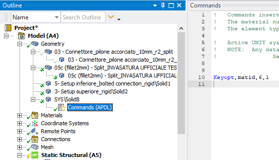
Now that I have opened the archive, I see you are using hyperelastic materials. The inner liner part is modeled with Silicon Rubber. That would benefit from Keyop(6)=1 that would turn on the mixed u-P element formulation and the reduced integration scheme. The keyop is done by a Commands object and looks like this:
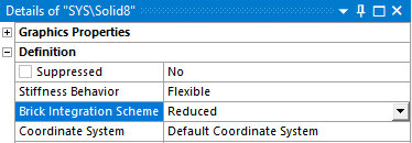
 In the details window, change the Brick Integration Scheme to Reduced.
 It is generally unacceptable for solid elements to have only one element through the thickness, and that is the condition on the inner liner part.
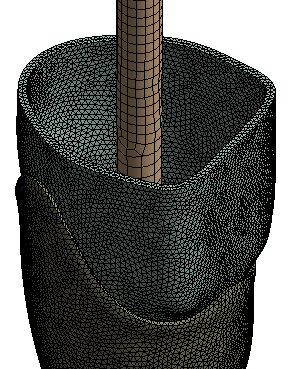
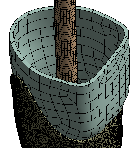 A minimum of two elements through the thickness is required and more is better. With some effort, the inner liner part could be made using hex elements which would reduce slightly the number of elements.
 Since the steel parts are much stiffer than the nylon and silicon parts, change the steel parts to rigid behavior to use fewer nodes and elements.
This model has a large Coefficient of Friction. The solver issues a message to say
 You can do that under Analysis Settings, but that is only needed if the convergence is failing. If it solves with the Program Controlled setting, that is a slightly faster solver.
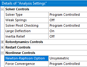 One of the best changes you can make to this model is to not use 24 steps, but use 2 steps. Step 1 is to tighten the bolts. Step 2 is to apply the force. The the Step Controls can be Auto Time Stepping On.
Looking at the Bonded Contact between the steel shaft and the inside of the inner liner. I would have modeled the resin as solid elements instead of using beam elements to connect nodes on the shaft to nodes on the inside of a very soft silicon rubber material.
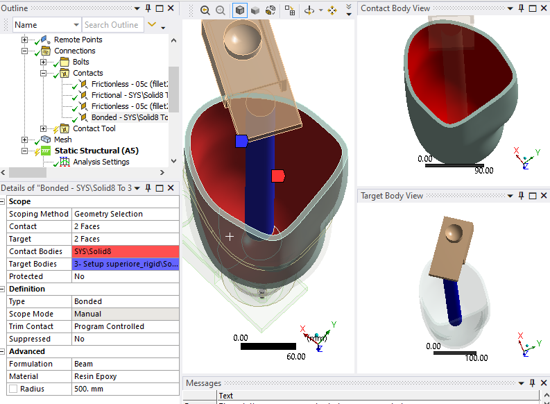 In a few clicks, you can do a Volume Extract in SpaceClaim to model the epoxy resin.
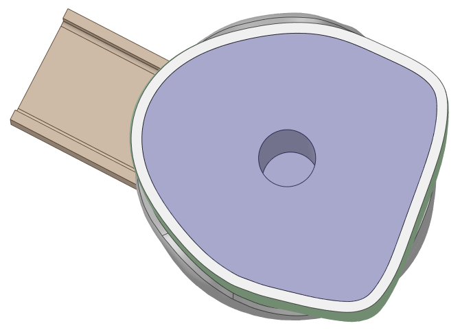 Drag the solid out of the Volume component, and put it next to Solid8, hide the other components and use the Share button on the Workbench tab to avoid having to use Bonded Contact.
I downloaded your archive and opened it. I see the number of nodes and elements (306k, 248k) are too large for the Student license. Fortunately, I have a full license for 2020 R1. Unfortunately, if you are using an older version, you won't be able to open my archive.
Now that I have opened the archive, I see you are using hyperelastic materials. The inner liner part is modeled with Silicon Rubber. That would benefit from Keyop(6)=1 that would turn on the mixed u-P element formulation and the reduced integration scheme. The keyop is done by a Commands object and looks like this:
 In the details window, change the Brick Integration Scheme to Reduced.
 It is generally unacceptable for solid elements to have only one element through the thickness, and that is the condition on the inner liner part.
 A minimum of two elements through the thickness is required and more is better. With some effort, the inner liner part could be made using hex elements which would reduce slightly the number of elements.
 Since the steel parts are much stiffer than the nylon and silicon parts, change the steel parts to rigid behavior to use fewer nodes and elements.
This model has a large Coefficient of Friction. The solver issues a message to say
 You can do that under Analysis Settings, but that is only needed if the convergence is failing. If it solves with the Program Controlled setting, that is a slightly faster solver.
 One of the best changes you can make to this model is to not use 24 steps, but use 2 steps. Step 1 is to tighten the bolts. Step 2 is to apply the force. The the Step Controls can be Auto Time Stepping On.
Looking at the Bonded Contact between the steel shaft and the inside of the inner liner. I would have modeled the resin as solid elements instead of using beam elements to connect nodes on the shaft to nodes on the inside of a very soft silicon rubber material.
 In a few clicks, you can do a Volume Extract in SpaceClaim to model the epoxy resin.
 Drag the solid out of the Volume component, and put it next to Solid8, hide the other components and use the Share button on the Workbench tab to avoid having to use Bonded Contact.

