TAGGED: boundary-conditions
-
-
April 20, 2021 at 5:44 pm
afshiin.a
Subscriber
Hello.nI have a question. nI want to know how much the distance between the PML boundary conditions and the waveguide?nI wanted to know the optimal distance for simulation. for example FDTD, VarFDTD and FDE. n If the distance is large, the volume of the simulation area increases. Therefore the simulation time increases. Otherwise, if the distance between the boundary conditions and the waveguide is small, there is a possibility of error in the results.nPlease guide me. n
-
April 21, 2021 at 7:32 am
Shelley
SubscriberIf the figure you draw contains substrate, it may be easy to understand. Generally speaking, the distance between PML boundary and structure is half a wavelength at least. In addition, the PML boundary below should cut off substrate. FDE should be big enough to avoid mode cut-off.n -
April 21, 2021 at 9:12 am
afshiin.a
SubscriberThanks for your answer.nYes, according to your answer, I have put the substrate in the figure. Now I have specified the distance in the figures. Please determine that they are drawn correctly?.Besides, I have two questions. n1- If the wavelength range,(1530 nm - 1560 nm), is considered instead of a wavelength, should be the distance from the boundary condition to the waveguide at least half the wavelength greater? nFor example in wavelength range (1530 - 1560), distance <= 1560/2.nn2- Also, in the figure related to the cross-section in the coordinates (y-z), if the upper boundary condition is the metal type, what should be the distance boundary condition metal to the waveguide? Is it possible to consider the PML boundary condition for metal? n
n
-
April 21, 2021 at 3:34 pm
Kyle
Ansys EmployeenThis topic is discussed in the post here: /forum/discussion/24201/ansys-insight-key-fdtd-simulation-settingsnHere is the relevant section:nSimulation spannThe span of the FDTD region should be set such that PML boundaries are a half wavelength away from the sides of any geometry objects in the simulation. “Wavelength” here refers to the longest wavelength in the source spectrum, taking into account the refractive index of the material between the object and the boundary. Exceptions to this rule include substrates, cladding, or any other objects that are supposed to extend beyond the simulation region (for example, the ends of input/output waveguides). For example, in a simulation of a simple straight waveguide in the Z direction:n
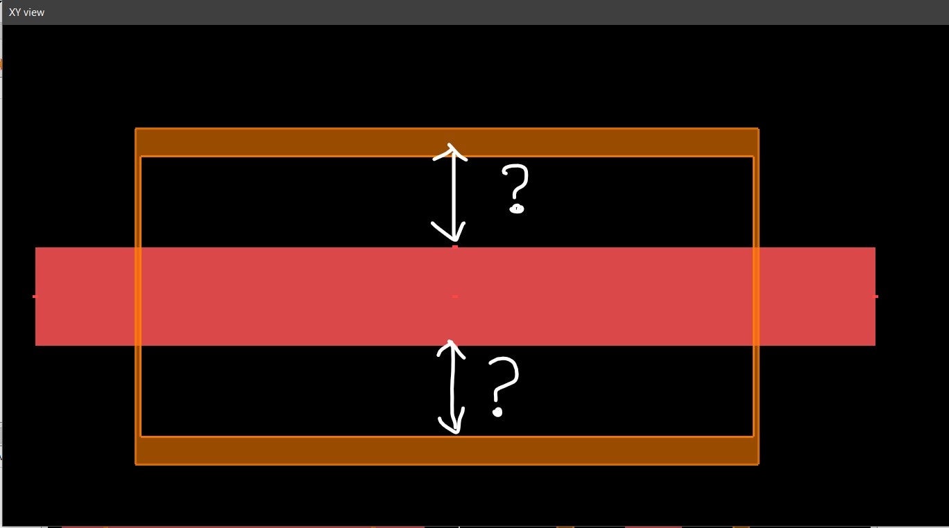
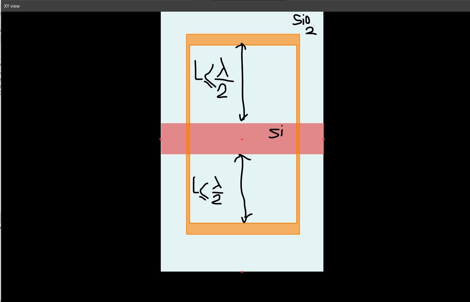
XY cross-sectionn• Substrate extends through the X max/min and Y min boundaries.n• X max/min and Y max PML boundaries are at least a half wavelength away from the sides of the waveguides.n
nn
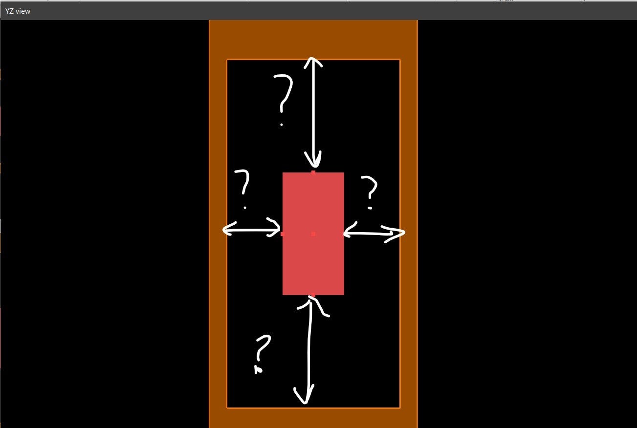
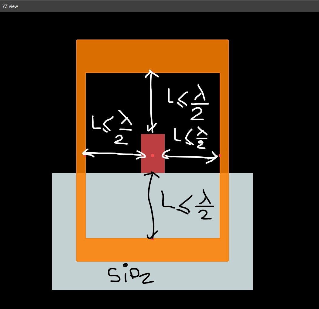
XZ cross-sectionn• The ends of the waveguides extend through the Z max/min boundaries.n
nTo answer your questions:n1) You should consider the longest wavelength in the spectrum when setting the simulation span.n2) The rule of thumb for metal boundaries should be the same as the rule for PML boundaries.nAlso, note that these are just guidelines. The final simulation spans should be determined using convergence testing.n
-
April 22, 2021 at 11:23 am
-
April 23, 2021 at 12:35 am
Kyle
Ansys EmployeeYou're welcome!n
-
Viewing 5 reply threads
- The topic ‘The distance between the PML boundary condition and the waveguide’ is closed to new replies.
Innovation Space
Trending discussions
Top Contributors
-
6455
-
1906
-
1457
-
1308
-
1022
Top Rated Tags
© 2026 Copyright ANSYS, Inc. All rights reserved.
Ansys does not support the usage of unauthorized Ansys software. Please visit www.ansys.com to obtain an official distribution.