

-
-
April 14, 2021 at 3:09 am
Danielgkh
SubscriberHi,
I am running a CFD simulation on the exhaust gas system for Micro CHP. The design I am working on functions mainly as the muffler for the exhaust gas, but also as a secondary heat exchanger. It consists of a double pipe, with exhaust gas flowing in the inner pipe and coolant-water-mixture flowing in the cavity between the inner pipe and outer pipe.
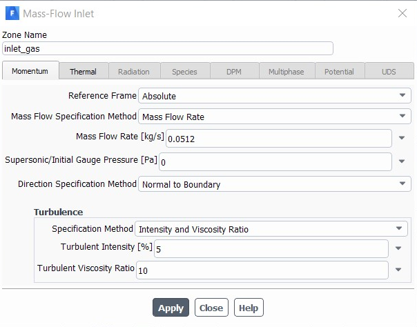
My model is basically just 2 fluid domains in contact with each other, with coupled thin wall in between them. I am using realizable k-epsilon model with scalable wall function. Energy is on, species transport is also on, with default setting. I didnt change any of the properties of the material other than mixing the coolant-water-mixture in mixture template(leaving everything as default). I am using mass-flow-inlet for both the inlet and pressure outlet for both the outlet. Here are the screenshots of each inlet and outlet.
April 14, 2021 at 4:06 pmRob
Forum ModeratorAny/all of the things you mention can play a part in accuracy. Also consider if you're modelling the same thing that you have built. nApril 19, 2021 at 6:31 amSubscriberHi Rob, thanks for your quick reply. nAfter running a lot more simulations with different settings, i found out a few possible reason, but i am not really sure how to solve it.nAfter inspecting the pathline of water from the water inlet, it seems as though the water is travelling on a single path towards the outlet and not filling up the whole cavity. (The water is supposed to fill up the whole cavity while swirling around the inner pipe to reach the outlet.) From the temperature contour, it also shows the same result. Only where the pathline of water touches the inner pipe has a higher temperature which means heat is transfered from the hot gas to the cold water. For all other places, even though there's heat transfer happening, they have a lower temperature which I think it's just convection but not conduction. nAlso from the pathline, a few of my simulation turn out to have totally incomplete pathline which I assume it's due to reverse flow. I have move my outlet further downstrem but it doesnt really help much. when running calculation, the reverse flow message still keeps on appearing.nFrom the temperature contour, i realized there's somehow a lower temperature near the region of outlet which caused the outlet temperature higher than the inlet temperature, which is not possible. Does the specified backflow temperature plays a role in this? I have set mine to 20C. Should I set it nearer to the estimated outlet temperature?n(Here is a rough sketch of my design)n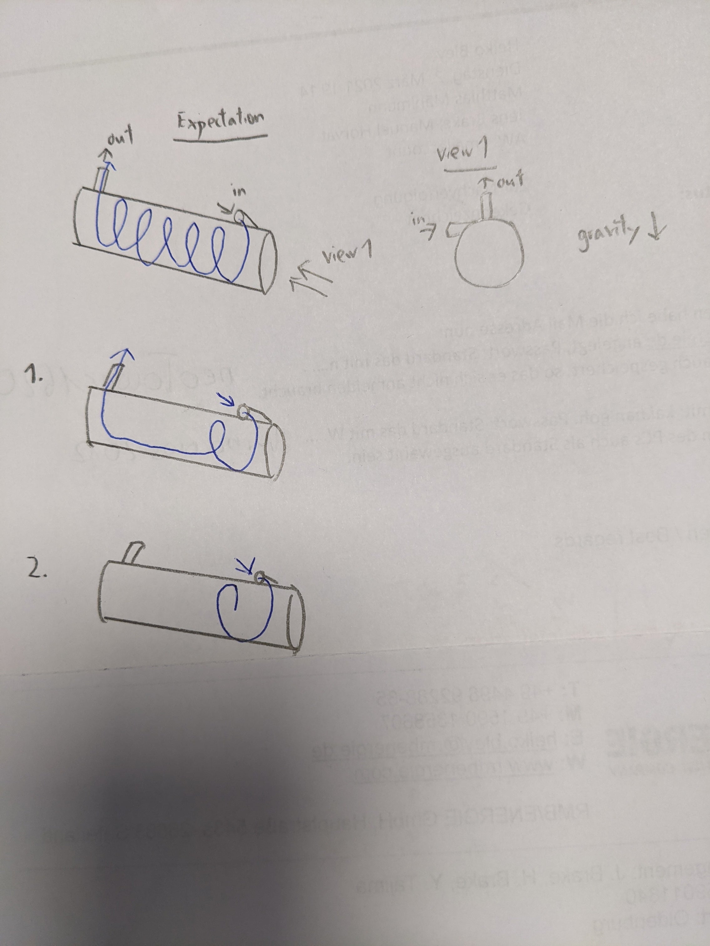 nDoes any of these reason even possible, especially the first one? I will be really grateful if you can advice me on this matter. Thanksn
April 19, 2021 at 6:36 am
nDoes any of these reason even possible, especially the first one? I will be really grateful if you can advice me on this matter. Thanksn
April 19, 2021 at 6:36 amDrAmine
Ansys EmployeeWhat is the EOS of the liquid mixture? (as you said everything is set to default I am sure that it is not correct for liquid mixtures)nBackflow quantities does only affect the flow if backflow occurs? Are you seeing backflow occurring?nApril 19, 2021 at 7:03 amSubscriberHi DrAmine,nhere's the EOS of my current liquid mixture, I did change some of the setting since last week. The mixture is a 60:40 mixture of water and ethylenglykol, with a mass diffusion coefficients of 1.87e-05 for ethylenglykol in water.n n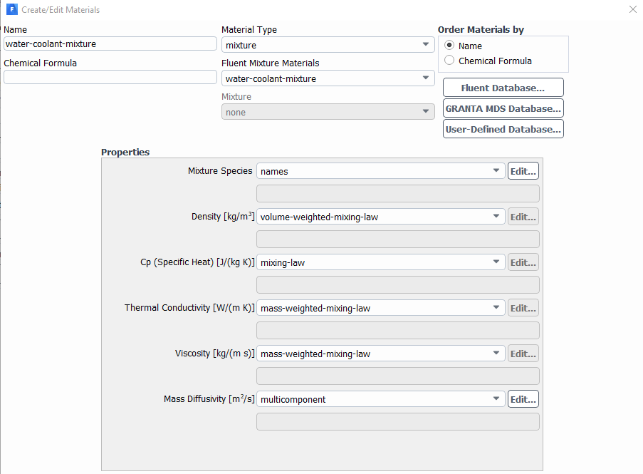 How do I actually check for backflow? I don't notice any backflow graphically. It was based on the assumption fromnTemperature contour, with lower temperature at outletnPathline, the path is incomplete which might due to the backflow pressing against itnMessage during calculation, although the area affected is not that large, around 10% of outlet face. Theres's also times where there's no reverse flow message showing up at all.n
April 19, 2021 at 7:36 amSubscriberSorry, I have just checked the vectors at the outlet, I dont see any signs of backflow, but the pathlines of water is still incomplete(2nd example), what could have caused this?nApril 19, 2021 at 7:41 amAnsys EmployeeDoes Fluent report incomplete steps when trying to show pathlines? If yes then try to increase the steps.nCan you paste a screenshot of the Mass Flux Report?nApril 19, 2021 at 8:23 amSubscriberYes, for example number created: 84, incomplete: 84. nWhen I keep on increasing the steps, following message wil appear number tracked = 84, incomplete = 80, incomplete_parallel = 4 Please consider reducing rpvar dpm/parallel/loop-factor to reduce the number of incomplete tracks in parallel. Current value is 10Should I do as it says? nHere's the mass Flux Reportn
How do I actually check for backflow? I don't notice any backflow graphically. It was based on the assumption fromnTemperature contour, with lower temperature at outletnPathline, the path is incomplete which might due to the backflow pressing against itnMessage during calculation, although the area affected is not that large, around 10% of outlet face. Theres's also times where there's no reverse flow message showing up at all.n
April 19, 2021 at 7:36 amSubscriberSorry, I have just checked the vectors at the outlet, I dont see any signs of backflow, but the pathlines of water is still incomplete(2nd example), what could have caused this?nApril 19, 2021 at 7:41 amAnsys EmployeeDoes Fluent report incomplete steps when trying to show pathlines? If yes then try to increase the steps.nCan you paste a screenshot of the Mass Flux Report?nApril 19, 2021 at 8:23 amSubscriberYes, for example number created: 84, incomplete: 84. nWhen I keep on increasing the steps, following message wil appear number tracked = 84, incomplete = 80, incomplete_parallel = 4 Please consider reducing rpvar dpm/parallel/loop-factor to reduce the number of incomplete tracks in parallel. Current value is 10Should I do as it says? nHere's the mass Flux Reportn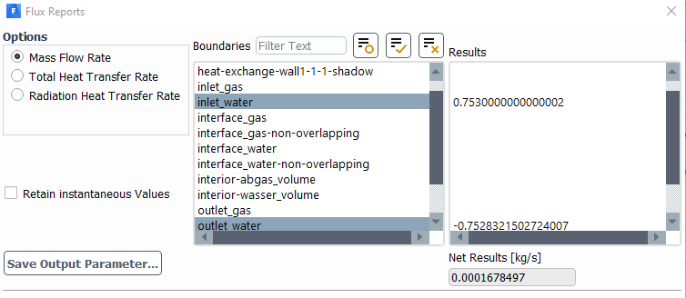 nOn side notes, I am referencing/initializing/computing my simulation from gas inlet, not water inlet, not all zones. For solutions methods, it's SIMPLE, Green-Gauss Node based and all others set to second order. I had also change one setting for the EOS for air in gas domain, density: from constant to incompressible-ideal-gas. Not sure if any of these makes a difference.n
April 19, 2021 at 8:43 amForum ModeratorLooking at the flow pattern you'll need a lot of steps to get the pathlines through the domain. The default is a good starting point in most models but here you're swirling to expect to need many more steps. If they're incomplete with 1000 steps for one twist work out roughly how many you'll need for the full length. Ignore incomplete-parallel, it just means a pathline has crossed a partition too many times:again it's a feature of your model & flow so if most pathlines exit as planned with more steps we don't need to fix it. nGiven the swirl is sustained, review the mesh in the bulk flow. Boundary layer is important for heat transfer, but it's the bulk mesh that will stop jet diffusion. This is one of the few cases I've seen on here where an O-grid might actually be worth using: I'd have used a polar mesh many many years ago. For post processing, set the cell zone centre of rotation (cell zone condition) and use the axial, tangential & radial components to help understand what's going on. nApril 19, 2021 at 9:29 amSubscriberI might have been exaggerated in my attached drawing, but I am expecting to have 4 twist as there are 4 fins inside the fluid domain to assist in the swirling action. The default steps was 500, I have now increased it up to 99999, but still, the pathlines look almost the same with just a few additional lines and only a few of them manage to complete one twist. So, i'm guessing this method doesn't work.nDue to student license limitation and also the geometry (fins inside water domain), I am currently using quite a rough tetra mesh with 3 inflation layers on every surface. O-grid might be hard to implement, as the fins are blocking the path for sweep. I have tried hexa dominant, but it doesnt really catch any detail for the boundary layers. Given that this domain is in a hollow cylinder shape, I'd say O-grid has the same meshing as polar mesh.nHowever let me try meshing with O-grid again or even remove the fins altogether. This might cause inaccurate result, but anyhow, this water domian is my secondary concern. As long as it reduce the temperature of my gas domain even more, how the fluid flows inside can be ignored. In my opinion as a newbie in this field...ArraynViewing 9 reply threads
nOn side notes, I am referencing/initializing/computing my simulation from gas inlet, not water inlet, not all zones. For solutions methods, it's SIMPLE, Green-Gauss Node based and all others set to second order. I had also change one setting for the EOS for air in gas domain, density: from constant to incompressible-ideal-gas. Not sure if any of these makes a difference.n
April 19, 2021 at 8:43 amForum ModeratorLooking at the flow pattern you'll need a lot of steps to get the pathlines through the domain. The default is a good starting point in most models but here you're swirling to expect to need many more steps. If they're incomplete with 1000 steps for one twist work out roughly how many you'll need for the full length. Ignore incomplete-parallel, it just means a pathline has crossed a partition too many times:again it's a feature of your model & flow so if most pathlines exit as planned with more steps we don't need to fix it. nGiven the swirl is sustained, review the mesh in the bulk flow. Boundary layer is important for heat transfer, but it's the bulk mesh that will stop jet diffusion. This is one of the few cases I've seen on here where an O-grid might actually be worth using: I'd have used a polar mesh many many years ago. For post processing, set the cell zone centre of rotation (cell zone condition) and use the axial, tangential & radial components to help understand what's going on. nApril 19, 2021 at 9:29 amSubscriberI might have been exaggerated in my attached drawing, but I am expecting to have 4 twist as there are 4 fins inside the fluid domain to assist in the swirling action. The default steps was 500, I have now increased it up to 99999, but still, the pathlines look almost the same with just a few additional lines and only a few of them manage to complete one twist. So, i'm guessing this method doesn't work.nDue to student license limitation and also the geometry (fins inside water domain), I am currently using quite a rough tetra mesh with 3 inflation layers on every surface. O-grid might be hard to implement, as the fins are blocking the path for sweep. I have tried hexa dominant, but it doesnt really catch any detail for the boundary layers. Given that this domain is in a hollow cylinder shape, I'd say O-grid has the same meshing as polar mesh.nHowever let me try meshing with O-grid again or even remove the fins altogether. This might cause inaccurate result, but anyhow, this water domian is my secondary concern. As long as it reduce the temperature of my gas domain even more, how the fluid flows inside can be ignored. In my opinion as a newbie in this field...ArraynViewing 9 reply threads- The topic ‘Inaccurate heat transfer between fluids’ is closed to new replies.
Innovation Space Trending discussions
 Top Contributors
-
peteroznewman
 6515
6515 -
scabo
 1906
1906 -
Dennis Chen
 1463
1463 -
javat33489
 1309
1309 -
Shyam Prasad V Atri
1022
Top Rated Tags
© 2026 Copyright ANSYS, Inc. All rights reserved.
Ansys does not support the usage of unauthorized Ansys software. Please visit www.ansys.com to obtain an official distribution.
-
Ansys Assistant will be unavailable on the Learning Forum starting January 30. An upgraded version is coming soon. We apologize for any inconvenience and appreciate your patience. Stay tuned for updates.


 You are navigating away from the AIS Discovery experience