

TAGGED: mesh
-
-
March 14, 2021 at 3:17 pm
sophiemcg
SubscriberI am trying to model the cylindrical scaffold as shown in black and white according to the one shown in blue in Ansys Workbench. The one shown in blue was created in Abaqus and used mesh CD310, 10 node quadratic tetrahedral elements.
I have tried to insert edge sizing along the edges and circle faces. I have also added method>tetrahedrons>quadratic and it is still not looking anything like the one generated in abaqus.
Thank you.
March 14, 2021 at 3:41 pmpeteroznewman
SubscribernIt looks like the element size is too large in your mesh. nThe ABAQUS mesh looks like the element size is about 1/3 or 1/4 of the diameter of the rods.nDid you leave your element size at Default?n Type in the value that represents 1/3 of the diameter where the word Default appears.n
March 14, 2021 at 8:18 pmSubscriberHi, nThanks so much that has helped a lot! nI now have the mesh shown. nI still cannot get the elements on the face of the circles to appear as they do in the above model (also some vary from each other). nI also need the top face to be split in 2 as shown in the image above. I have tried edge sizing along both the long and short edge and neither worked.nAdditionally, the circles located on the top layer did not change from the original mesh I had - they always seem to appear originating at the centre and pointing outwards. nDo you have any suggestions for the above issues. Thanks in advance. n
Type in the value that represents 1/3 of the diameter where the word Default appears.n
March 14, 2021 at 8:18 pmSubscriberHi, nThanks so much that has helped a lot! nI now have the mesh shown. nI still cannot get the elements on the face of the circles to appear as they do in the above model (also some vary from each other). nI also need the top face to be split in 2 as shown in the image above. I have tried edge sizing along both the long and short edge and neither worked.nAdditionally, the circles located on the top layer did not change from the original mesh I had - they always seem to appear originating at the centre and pointing outwards. nDo you have any suggestions for the above issues. Thanks in advance. n n
March 14, 2021 at 9:00 pmSubscribernWhy do you need the same mesh on the circular face as the Abaqus mesh?nCan you get the Abaqus mesh file so that you get the exact same nodes and elements?nI don't see the split line you are talking about.nMarch 14, 2021 at 9:41 pmSubscriberI am trying to validate my model (b+w) by comparing my results to the ones seen in the paper (blue) to ensure that my FEA representation is accurate. I will then be changing material properties etc. to investigate their effects. I am very close to getting identical results as the paper, however, I would like to get my mesh as close to theirs as I can to get my results the same.nThe number of elements in the Abaqus mesh was 1,894,283. My model currently has 2,700,500. nI have attached a photo of what I mean by the split line n
n
March 14, 2021 at 9:00 pmSubscribernWhy do you need the same mesh on the circular face as the Abaqus mesh?nCan you get the Abaqus mesh file so that you get the exact same nodes and elements?nI don't see the split line you are talking about.nMarch 14, 2021 at 9:41 pmSubscriberI am trying to validate my model (b+w) by comparing my results to the ones seen in the paper (blue) to ensure that my FEA representation is accurate. I will then be changing material properties etc. to investigate their effects. I am very close to getting identical results as the paper, however, I would like to get my mesh as close to theirs as I can to get my results the same.nThe number of elements in the Abaqus mesh was 1,894,283. My model currently has 2,700,500. nI have attached a photo of what I mean by the split line n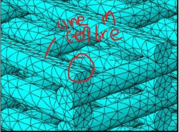
 n
March 14, 2021 at 10:22 pmSubscribernIn SpaceClaim, or any other CAD editor, split that face. I would create a plane and use the Split button.nResults should be mesh independent. You can use a larger element size to get closer to the Abaqus node count.nMarch 15, 2021 at 10:00 pmSubscribernHi, nI cannot seem to split the face using SolidWorks but I may just leave it as it. nRegarding the circular faces - do you have any suggestions for making them look more like the abaqus model - the elements are a lot more evenly spaced out in that model compared to mine. I have tried face sizing and edge sizing along the circles.nApologies for all the questions - Thanks so much nMarch 15, 2021 at 10:25 pmSubscribernANSYS meshing software creates valid elements for its solver. ABAQUS meshing does the same. The elements are valid in both cases. There is no reason to force the ANSYS mesh to look exactly like the ABAQUS mesh. They are just different.nViewing 7 reply threads
n
March 14, 2021 at 10:22 pmSubscribernIn SpaceClaim, or any other CAD editor, split that face. I would create a plane and use the Split button.nResults should be mesh independent. You can use a larger element size to get closer to the Abaqus node count.nMarch 15, 2021 at 10:00 pmSubscribernHi, nI cannot seem to split the face using SolidWorks but I may just leave it as it. nRegarding the circular faces - do you have any suggestions for making them look more like the abaqus model - the elements are a lot more evenly spaced out in that model compared to mine. I have tried face sizing and edge sizing along the circles.nApologies for all the questions - Thanks so much nMarch 15, 2021 at 10:25 pmSubscribernANSYS meshing software creates valid elements for its solver. ABAQUS meshing does the same. The elements are valid in both cases. There is no reason to force the ANSYS mesh to look exactly like the ABAQUS mesh. They are just different.nViewing 7 reply threads- The topic ‘How to mesh this cylindrical model as shown?’ is closed to new replies.
Ansys Innovation Space Trending discussions
 Top Contributors
-
peteroznewman
 3024
3024 -
javat33489
 971
971 -
Shyam Prasad V Atri
 857
857 -
scabo
 815
815 -
adib.aktab999
777
Top Rated Tags
© 2025 Copyright ANSYS, Inc. All rights reserved.
Ansys does not support the usage of unauthorized Ansys software. Please visit www.ansys.com to obtain an official distribution.
-


The Ansys Learning Forum is a public forum. You are prohibited from providing (i) information that is confidential to You, your employer, or any third party, (ii) Personal Data or individually identifiable health information, (iii) any information that is U.S. Government Classified, Controlled Unclassified Information, International Traffic in Arms Regulators (ITAR) or Export Administration Regulators (EAR) controlled or otherwise have been determined by the United States Government or by a foreign government to require protection against unauthorized disclosure for reasons of national security, or (iv) topics or information restricted by the People's Republic of China data protection and privacy laws.


