-
-
March 7, 2021 at 8:10 pm
p43kumar
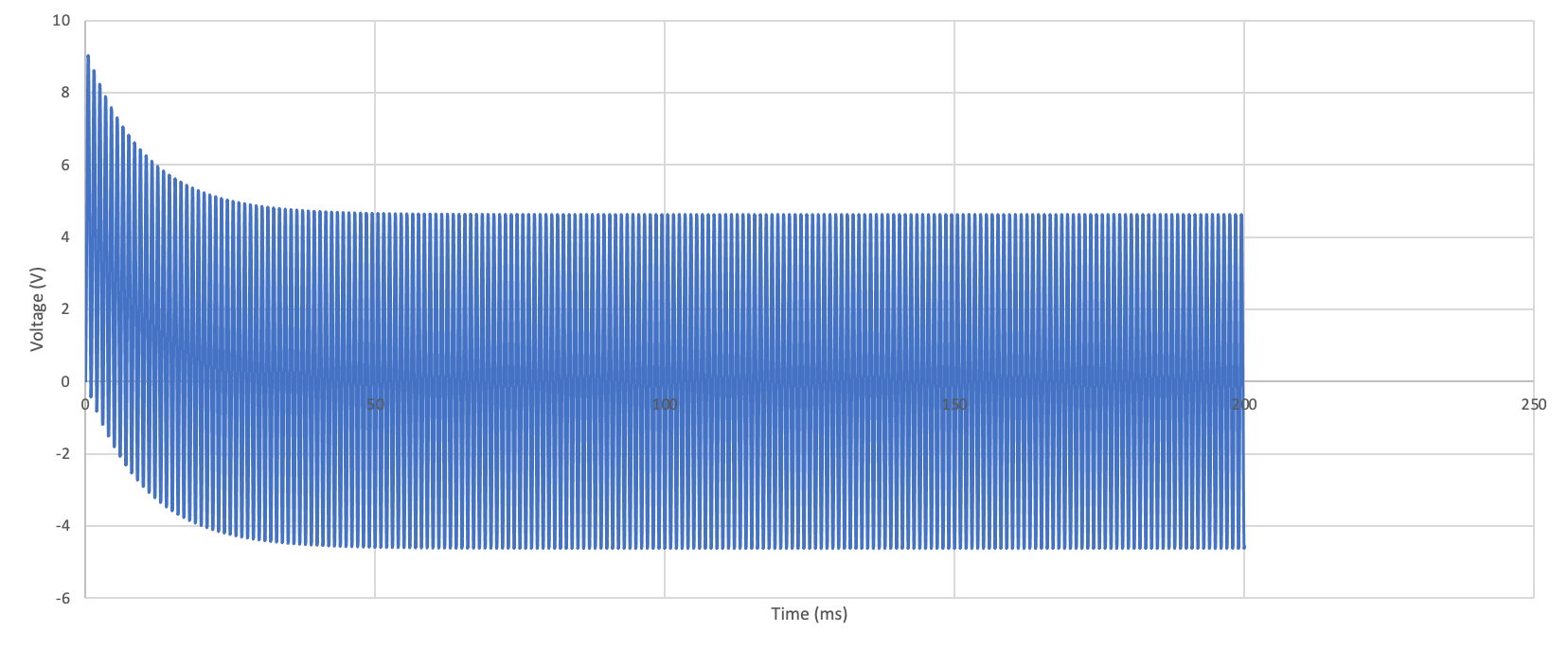
SubscriberThe system studied here (fig. 1) is a 2 coil setup embedded within a pure iron core. The setup can be treated like an Resistor and inductor system. A capacitor is added in parallel to reduce the impedance experienced by the system (fig. 2). A voltage source of 300 V at 1000 Hz is suppling the input to the system. By having a capacitor in parallel, there is a significant voltage drop experienced. The plot of the voltage reduction is shown in the fig. 3. The simulation was also ran for 200 ms with a 100 mF capacitor in parallel to ensure that steady state was achieved, as shown in fig. 4. I was wondering if someone could help me understand why this voltage drop occurs?
blob:/forum/1fba9a80-92fa-4575-ac2d-051303982712Fig. 1. 2 coil system
blob:/forum/75252dc0-504a-47b1-ad5f-90ff2d38144bFig. 2. Circuit employed in ANSYS Maxwell Simplorer and linked to the model
blob:/forum/14492ff0-b509-484b-ad3e-0b8c64eea6faFig. 3. Voltage plots with different capacitor
March 10, 2021 at 5:12 pmicellb1
Ansys EmployeeHi, nCould you re-upload images for Fig.1 Fig.2 and Fig.3? They are not showing. Thanks.nnViewing 1 reply thread- The topic ‘Reduced Voltage due to Capacitor in parallel’ is closed to new replies.
Ansys Innovation Space Trending discussions
 Top Contributors
-
peteroznewman
 3597
3597 -
scabo
 1208
1208 -
Dennis Chen
 1092
1092 -
javat33489
 1068
1068 -
Shyam Prasad V Atri
952
Top Rated Tags
© 2025 Copyright ANSYS, Inc. All rights reserved.
Ansys does not support the usage of unauthorized Ansys software. Please visit www.ansys.com to obtain an official distribution.
-

Electronics
Topics related to HFSS, Maxwell, SIwave, Icepak, Electronics Enterprise and more.
Reduced Voltage due to Capacitor in parallel


Ansys Assistant

Welcome to Ansys Assistant!
An AI-based virtual assistant for active Ansys Academic Customers. Please login using your university issued email address.

Hey there, you are quite inquisitive! You have hit your hourly question limit. Please retry after '10' minutes. For questions, please reach out to ansyslearn@ansys.com.
RETRY