-
-
March 4, 2021 at 10:57 pm
akban
SubscriberHi,
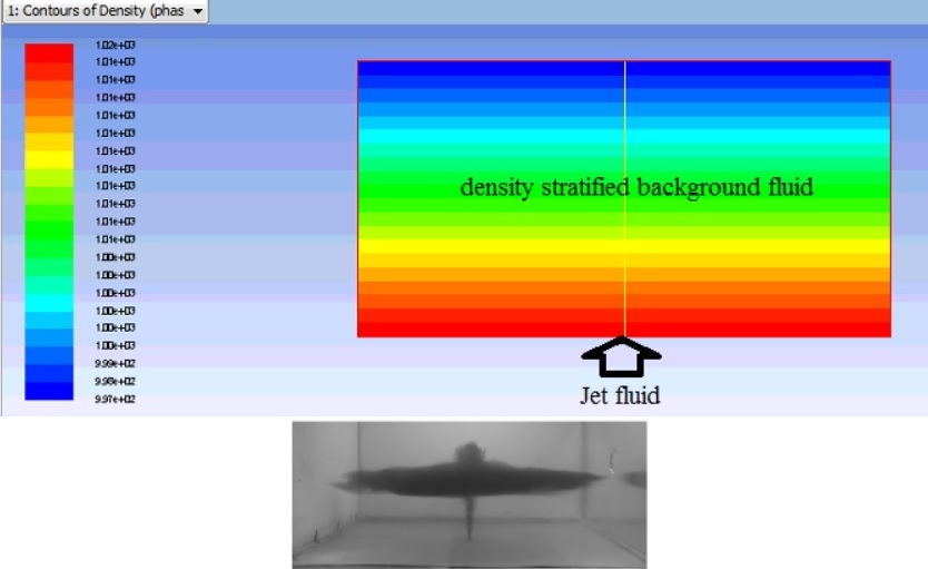
I wish to simulate development of buoyant jet in a density stratified medium.
In my system, background density varies linearly from bottom (high) to top (low). Thereafter a jet of medium density is opened from bottom. So it should move up and at a neutral layer, the jet fluid should spread horizontally. Background fluid is water with varying density. At bottom density is 1016 kg/mt3 and at top density is 1001 kg/mt3 . Water of density 998 .3 kg/mt3 is impinged from bottom as round jet.
I am adding two images to clarify my system.
1st image shows a tank full of water (density stratified as shown by different colours). Then a constant density water jet is impinged from bottom (shown by arrow). 2nd image shows experimental image that should be found in simulation.
March 4, 2021 at 11:07 pmYasserSelima
SubscriberWhat is the boundary condition at the top?.March 4, 2021 at 11:12 pmSubscriberNo slip condition, assuming top boundary is far from neutral layer.nMarch 5, 2021 at 1:42 amSubscriberwhat happens if you add incompressible fluid in a filled room?nMarch 5, 2021 at 9:30 amSubscriberYou mean my top boundary condition is wrong ? Should I use pressure outlet? or outflow?nMarch 5, 2021 at 11:27 amRob
Forum ModeratorPressure outlet is the better of the two options. You're adding mass into the domain so there has to be somewhere for it to go! nMarch 5, 2021 at 1:50 pmSubscriberEven with pressure outlet on the top, the simulation is not providing desirable outcome.nnThe background stratified density do not mix with incoming jet density.n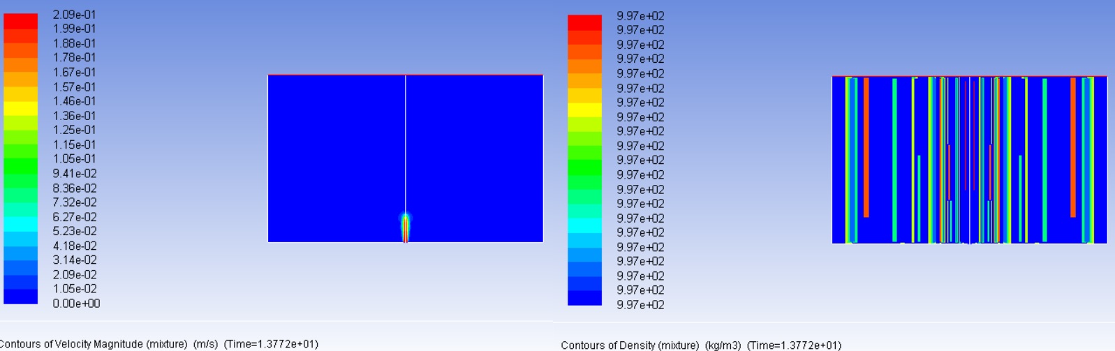 Please suggest.n
March 5, 2021 at 1:54 pmSubscriberCan you show contours of Volume fraction of the impinged water nMarch 6, 2021 at 10:51 amSubscriberPlease find contours of Volume fraction:nn
Please suggest.n
March 5, 2021 at 1:54 pmSubscriberCan you show contours of Volume fraction of the impinged water nMarch 6, 2021 at 10:51 amSubscriberPlease find contours of Volume fraction:nn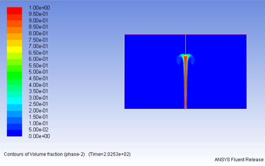 The jet fluid does not mix with background fluid.n
March 6, 2021 at 12:26 pmSubscriberIt does mix. Keep the simulation running for some more time.nBTW, 202 seconds in two phase flow is a very large time. What is your time step?nMarch 6, 2021 at 12:38 pmSubscriberMy time step is 0.002.nnIn experiment, it creates a horizontal layer of fluid at neutrally buoyant height within 120 sec.nMarch 6, 2021 at 12:47 pmSubscriberPlot void fraction of the dense water. (Not impinged) nIn the void fraction contours panel, uncheck the box auto range. Make the minimum 1e-06 and keep the maximum at 1. Then Select color map options and check the box log scale.nThis should give you a clearer view of how much the jet spread is.nMarch 6, 2021 at 4:31 pmSubscriberWhat is this check the box log scale ?nMarch 6, 2021 at 5:21 pmSubscriberAfter you select color-map option ... you will find a box Log scale ... check it and press ok ... then plot the contoursnMarch 6, 2021 at 5:35 pmSubscriber
The jet fluid does not mix with background fluid.n
March 6, 2021 at 12:26 pmSubscriberIt does mix. Keep the simulation running for some more time.nBTW, 202 seconds in two phase flow is a very large time. What is your time step?nMarch 6, 2021 at 12:38 pmSubscriberMy time step is 0.002.nnIn experiment, it creates a horizontal layer of fluid at neutrally buoyant height within 120 sec.nMarch 6, 2021 at 12:47 pmSubscriberPlot void fraction of the dense water. (Not impinged) nIn the void fraction contours panel, uncheck the box auto range. Make the minimum 1e-06 and keep the maximum at 1. Then Select color map options and check the box log scale.nThis should give you a clearer view of how much the jet spread is.nMarch 6, 2021 at 4:31 pmSubscriberWhat is this check the box log scale ?nMarch 6, 2021 at 5:21 pmSubscriberAfter you select color-map option ... you will find a box Log scale ... check it and press ok ... then plot the contoursnMarch 6, 2021 at 5:35 pmSubscriber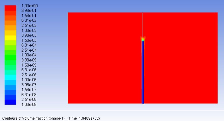
 n
March 6, 2021 at 5:51 pmSubscriberMake this contour phase with the same setting for phase 2. nMarch 6, 2021 at 5:54 pmSubscriber
n
March 6, 2021 at 5:51 pmSubscriberMake this contour phase with the same setting for phase 2. nMarch 6, 2021 at 5:54 pmSubscriber n
March 6, 2021 at 5:57 pmSubscriberIt should be like:nn
n
March 6, 2021 at 5:57 pmSubscriberIt should be like:nn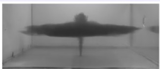 n
March 6, 2021 at 5:58 pmSubscriberMoreover, density contour looks total junk.nMarch 6, 2021 at 8:06 pmSubscriberWhy is density contours changing? How did you setup the density at the beginning?.You created UDF, this is what I see at the top. Where did you hookup the UDF?nMarch 6, 2021 at 9:10 pmSubscriber
n
March 6, 2021 at 5:58 pmSubscriberMoreover, density contour looks total junk.nMarch 6, 2021 at 8:06 pmSubscriberWhy is density contours changing? How did you setup the density at the beginning?.You created UDF, this is what I see at the top. Where did you hookup the UDF?nMarch 6, 2021 at 9:10 pmSubscriber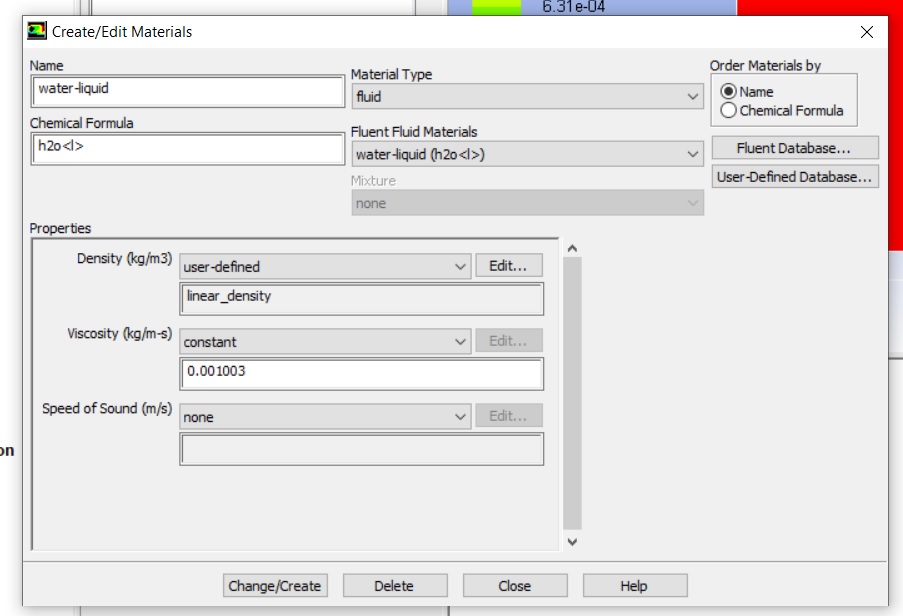 n
March 6, 2021 at 9:23 pmSubscriberyes, that is right. nAnd the density you showed at the top of this post was showing linear distribution. nCan you show contours of density of phase 1 at the current time. Phase 1, not mixturennMarch 6, 2021 at 9:28 pmSubscriberNo change. Very strangenn
n
March 6, 2021 at 9:23 pmSubscriberyes, that is right. nAnd the density you showed at the top of this post was showing linear distribution. nCan you show contours of density of phase 1 at the current time. Phase 1, not mixturennMarch 6, 2021 at 9:28 pmSubscriberNo change. Very strangenn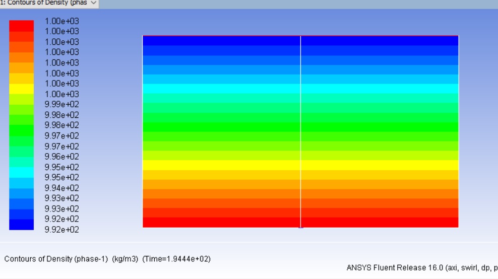 n
March 6, 2021 at 9:44 pmSubscriberIt should not change ... the mixture density is different. Now before explaining what is in my mind, I need to see phase-2 contours, log scale .. minimum 1e-12 and ...nLast thing, Regarding the experiment ... how did you get the linear density? How did you capture this image? PIV? or what?.March 6, 2021 at 9:52 pmSubscriber
n
March 6, 2021 at 9:44 pmSubscriberIt should not change ... the mixture density is different. Now before explaining what is in my mind, I need to see phase-2 contours, log scale .. minimum 1e-12 and ...nLast thing, Regarding the experiment ... how did you get the linear density? How did you capture this image? PIV? or what?.March 6, 2021 at 9:52 pmSubscriber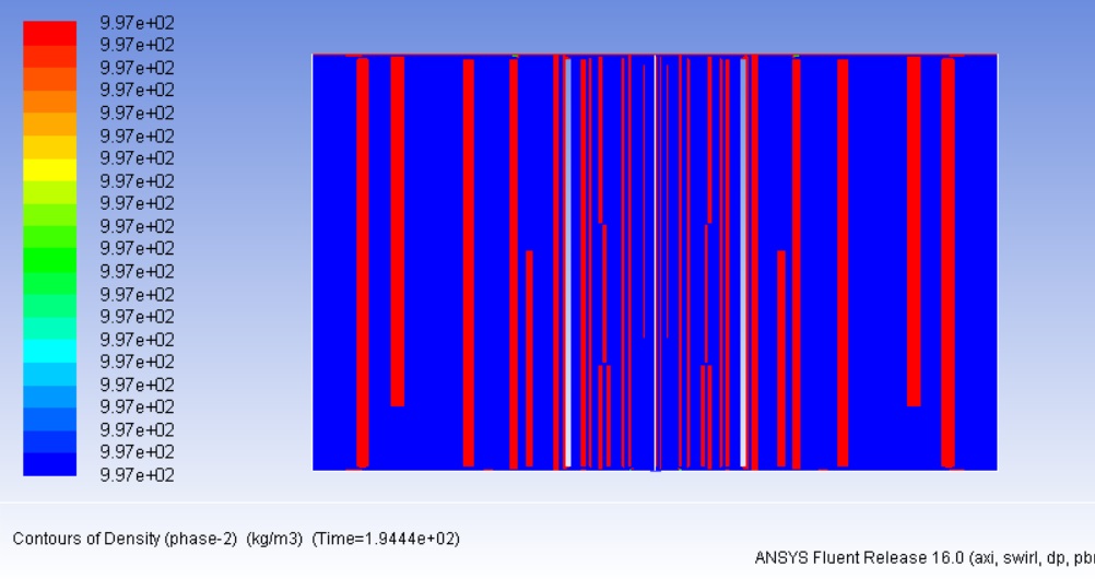 In experiment, linear density was created by using salt. The image is captured by a simple DSLR camera.n
March 6, 2021 at 10:03 pmSubscriberPhase 2 density looks junk.nBTW, what is in your mind?nMarch 6, 2021 at 10:06 pmSubscriberThe 2D simulation has an effect in obtaining this difference. Fluent recognises the jet depth is 1 m, which is not true ... To solve this issue, you need to have few cells in the z direction, , then apply symmetry plane. You can actually simulate 1 quarter of the room, and apply symmetry ... nMore smart solution ... make axisymmetry ... having rectangular or cylindrical room will not make a difference if it is large enough.nThe captured photo, the impinged fresh water particles, started to diffuse horizontally when the jet velocity became very small ... may be the salinity played a role.nFinally, I believe, if you left your simulation to continue, you might get something close to the photo .. nThe last density shows that the mixture density is similar to the impinged water density. I can't explain the physics of this ... it does not make sense . Probably this happened when you were running the simulation with wall at the top. !!nnmy recommendation, repeat the simulation ... asymmetric ... outlet pressure on top. And monitor the density in few points away from the jet.nMarch 6, 2021 at 10:17 pmSubscriberI do have pressure outlet on the top (I changed B.C after recommendation). My simulation is already axisymmetric. Now what should I do? I can add elements in z direction.nMarch 6, 2021 at 10:24 pmSubscriberaxisymmetric? where is your axis?nIf the simulation is axisymmetric already, you need to introduce the salinity into the simulation. Have water+salt mixture (patch the initial concentration) ... and impinge water nMarch 6, 2021 at 10:26 pmSubscriberIn the axisymmetric, X must be the axis. nMarch 6, 2021 at 10:55 pmSubscriberX is my vertical axis-- I have taken care of this.nWhy do I need to introduce the salinity into the simulation ? What is the problem if I have UDF of varying density?nHow do I make water+salt mixture ? Should I use species model ?.March 6, 2021 at 11:04 pmSubscriberYou need to introduce salinity because salinity difference causes diffusion. Nothing wrong with changing the density, but it did not replicate the experiment, so try to get closer to experiment.nYes, I would start by species model. Simple and it enables you to have mixture and pure water.March 7, 2021 at 8:13 pmSubscriberHi,nPlease suggest me how do I proceed to create salinity? nI chose species and mixing template. Then how should I choose materials to create salinity ?nPlease help.nMarch 8, 2021 at 1:03 amSubscriberyes switch on species transport, select volumetric and create a mixing template. Then press edit and you will be able to add material and specify density. You need to add the material in the material panel firs to find them when you select the mixture template nMarch 8, 2021 at 1:08 amSubscriberthis tutorial is the only one I can find using species. It is not close to yours as you don't have combustion nor reaction, but go through it quickly.nhttps://ansyshelp.ansys.com/account/secured?returnurl=/Views/Secured/corp/v202/en/flu_tg/flu_tg_magnus.htmlnMarch 9, 2021 at 11:47 pmSubscriberHi,nI can not open the tutorial. BTW, in the edit of mixture template, how do I create stratified salinity? n
In experiment, linear density was created by using salt. The image is captured by a simple DSLR camera.n
March 6, 2021 at 10:03 pmSubscriberPhase 2 density looks junk.nBTW, what is in your mind?nMarch 6, 2021 at 10:06 pmSubscriberThe 2D simulation has an effect in obtaining this difference. Fluent recognises the jet depth is 1 m, which is not true ... To solve this issue, you need to have few cells in the z direction, , then apply symmetry plane. You can actually simulate 1 quarter of the room, and apply symmetry ... nMore smart solution ... make axisymmetry ... having rectangular or cylindrical room will not make a difference if it is large enough.nThe captured photo, the impinged fresh water particles, started to diffuse horizontally when the jet velocity became very small ... may be the salinity played a role.nFinally, I believe, if you left your simulation to continue, you might get something close to the photo .. nThe last density shows that the mixture density is similar to the impinged water density. I can't explain the physics of this ... it does not make sense . Probably this happened when you were running the simulation with wall at the top. !!nnmy recommendation, repeat the simulation ... asymmetric ... outlet pressure on top. And monitor the density in few points away from the jet.nMarch 6, 2021 at 10:17 pmSubscriberI do have pressure outlet on the top (I changed B.C after recommendation). My simulation is already axisymmetric. Now what should I do? I can add elements in z direction.nMarch 6, 2021 at 10:24 pmSubscriberaxisymmetric? where is your axis?nIf the simulation is axisymmetric already, you need to introduce the salinity into the simulation. Have water+salt mixture (patch the initial concentration) ... and impinge water nMarch 6, 2021 at 10:26 pmSubscriberIn the axisymmetric, X must be the axis. nMarch 6, 2021 at 10:55 pmSubscriberX is my vertical axis-- I have taken care of this.nWhy do I need to introduce the salinity into the simulation ? What is the problem if I have UDF of varying density?nHow do I make water+salt mixture ? Should I use species model ?.March 6, 2021 at 11:04 pmSubscriberYou need to introduce salinity because salinity difference causes diffusion. Nothing wrong with changing the density, but it did not replicate the experiment, so try to get closer to experiment.nYes, I would start by species model. Simple and it enables you to have mixture and pure water.March 7, 2021 at 8:13 pmSubscriberHi,nPlease suggest me how do I proceed to create salinity? nI chose species and mixing template. Then how should I choose materials to create salinity ?nPlease help.nMarch 8, 2021 at 1:03 amSubscriberyes switch on species transport, select volumetric and create a mixing template. Then press edit and you will be able to add material and specify density. You need to add the material in the material panel firs to find them when you select the mixture template nMarch 8, 2021 at 1:08 amSubscriberthis tutorial is the only one I can find using species. It is not close to yours as you don't have combustion nor reaction, but go through it quickly.nhttps://ansyshelp.ansys.com/account/secured?returnurl=/Views/Secured/corp/v202/en/flu_tg/flu_tg_magnus.htmlnMarch 9, 2021 at 11:47 pmSubscriberHi,nI can not open the tutorial. BTW, in the edit of mixture template, how do I create stratified salinity? n n
March 10, 2021 at 2:49 amSubscriberTo open the tutorial, use the help button in fluent. This should open your browser. Copy the above link and paste it in the same page.nnViewing 36 reply threads
n
March 10, 2021 at 2:49 amSubscriberTo open the tutorial, use the help button in fluent. This should open your browser. Copy the above link and paste it in the same page.nnViewing 36 reply threads- The topic ‘Simulation of a buoyant jet in a density stratified medium’ is closed to new replies.
Innovation Space Trending discussions
 Top Contributors
-
peteroznewman
 5179
5179 -
scabo
 1838
1838 -
Dennis Chen
 1387
1387 -
javat33489
 1249
1249 -
Shyam Prasad V Atri
1021
Top Rated Tags
© 2026 Copyright ANSYS, Inc. All rights reserved.
Ansys does not support the usage of unauthorized Ansys software. Please visit www.ansys.com to obtain an official distribution.
-
Ansys Assistant will be unavailable on the Learning Forum starting January 30. An upgraded version is coming soon. We apologize for any inconvenience and appreciate your patience. Stay tuned for updates.