

-
-
January 14, 2021 at 1:07 pm
Raffael_Mitrou
SubscriberDear ANSYS community,
since I am a beginner in ANSYS and facing a complex problem here, I could really need some help from you.
My two-phase VOF simulation consists of a porous zone (40% porosity) and a tank (3D). Both are connected so that two eulerian fluids can pass in both directions. In the very beginning, the porous zone and the tank are purged with nitrogen (phase-1) at p=40mbar. At t=0 a defined amount of liquid (phase-2) is dosed into the tank through the pressure-inlet surface so that the tank is filled partially at p=1bar. Meanwhile, the liquid gets soaked into the porous zone. All other surfaces are no-slip walls, except for the symmetry plane. The overall goal is to investigate the time needed to reach "complete wetting" of the liquid within the porous zone.
January 14, 2021 at 2:21 pmKarthik Remella
AdministratorHi, nGrayed-out patch - You will first need to initialize your domain and then 'patch'. Click on Initialize first and you should be able to 'Patch'.nMesh check failed - please make sure you have 'Share Topology' active in your CAD. Please open the CAD file in SpaceClaim. In the WorkBench tab, you should see the option of 'Share'. This will avoid creating interfaces in your model and you should be able to obtain a conformal mesh.nKarthiknJanuary 14, 2021 at 4:49 pmSubscriberHello Karthik,nthank you for the fast support! nGrayed-out patch:Sadly this didn't help. I already initialized the domain before. So I tried a reset prior to initializing again, but this also didn't help. I thought that maybe this is connected to the share topology topic, so I gave it a try.nShare topology:After I activated share topology, I saved the geometry and got a problem message referring to the mesh. Now I probably need to do a new meshing, but I will keep you updated, how it went.nThanks anyways,nRaffaelnJanuary 18, 2021 at 1:41 pmAdministratorHmm, interesting! Sure, please try it and let me know.nYes, once you apply 'Share Topology' properly, you should not see any 'Connections' in WorkBench Meshing. You might need to change the meshing strategy too.nThank you.nKarthiknJanuary 18, 2021 at 3:26 pmSubscriberSo now I have a new mesh that is nicely aligned at the interface of the two bodies. I also checked skewness and orthogonality and that seemed to be alright.nThen I decided to open a new Fluid box and connect it to my updated geometry (with the shared topology activated), hoping to have fewer problems.nSo before I did all the general settings again in Fluent I first went for checking the mesh. But it still gives me various warnings.nFollowing is the warning referring to the BCs that I didn't even manually create. I think they were automatically defined and now Fluent wants those defined again?WARNING: Current Mesh is incompatible with mesh operations defined. Following zones are missing:nwall_back_cell-kontaktbereich-trg wall_front_cell-kontaktbereich-trg inlet_cell-kontaktbereich-trg outlet_void_volume-kontaktbereich-src wall_back_void_volume-kontaktbereich-src wall_front_void_volume-kontaktbereich-src wall-26 wall-27 wall-28 wall-29 wall-30 wall-31nnAnd the rest of the mesh check result:nnApplying mesh operation Change Zone TypenApplying mesh operation Change Zone Type [ 2 ]nZone not slit.nApplying mesh operation Change Zone Type [ 3 ]nApplying mesh operation Change Zone Type [ 4 ]nZone not slit.nApplying mesh operation Change Zone Type [ 5 ]nzone id/name/list [] Enter zone id/name/listnInvalid zone.nzone id/name [] nError: CAR: invalid argument [1]: wrong type [not a pair]nError Object: #fnWarning: Operation Change Zone Type [ 5 ] failed.nApplying mesh operation Change Zone Type [ 6 ]nzone id/name/list [] Enter zone id/name/listnInvalid zone.nzone id/name [] nError: CAR: invalid argument [1]: wrong type [not a pair]nError Object: #fnWarning: Operation Change Zone Type [ 6 ] failed.nApplying mesh operation Change Zone Type [ 7 ]nApplying mesh operation Change Zone Type [ 8 ]nApplying mesh operation Change Zone Type [ 9 ]nApplying mesh operation Change Zone Type [ 10 ]nzone id/name/list [] Enter zone id/name/listnInvalid zone.nzone id/name [] nError: CAR: invalid argument [1]: wrong type [not a pair]nError Object: #fnWarning: Operation Change Zone Type [ 10 ] failed.nApplying mesh operation Change Zone Type [ 11 ]nZone not slit.nApplying mesh operation Change Zone Type [ 12 ]nzone id/name/list [] Enter zone id/name/listnInvalid zone.nzone id/name [] nError: CAR: invalid argument [1]: wrong type [not a pair]nError Object: #fnWarning: Operation Change Zone Type [ 12 ] failed.nApplying mesh operation Change Zone Type [ 13 ]nApplying mesh operation Change Zone Type [ 14 ]nApplying mesh operation Change Zone Type [ 15 ]nApplying mesh operation Delete Mesh InterfacenError at host: 83755584nquire-adjacent-threads: wrong type argument[1] (thread)nnI think it has to do with the newly defined BCs. I just defined two surfaces (outlet_void_volume & inlet_cell) which represent the interface and they were the reason for the activation of share topology.nAny ideas what I could do next?nThank you in advance! nJanuary 18, 2021 at 3:30 pmRob
Forum ModeratorWhen you bring in a new mesh Fluent will try and apply the old boundary conditions. As some of these are now different (ie no interface) you'll get a few warnings. The CAR error means a required setting is missing somewhere. If you have two fluid zones check they're both fluid and one isn't solid due to the import. nJanuary 18, 2021 at 4:02 pmSubscriberPS: I used this video, explaining how to set up a porous media simulation: (297) ✅ ANSYS FLUENT - Porous Medium - TUTORIAL Part 4/4 - YouTube and how therefore to label the edges and interfaces. In the video at 01:20 min he creates the interfaces.nI followed it during labeling the edges/surfaces in my case. Maybe I do need to specify the interface between the porous zone (BC: inlet_cell) and the tank zone (outlet_void_volume). nBUT I can't see the Mesh Interface tab within the main list at the left (outline view). And the tab under Domain > Interfaces > Mesh... is greyed-out. Any ideas why this is?n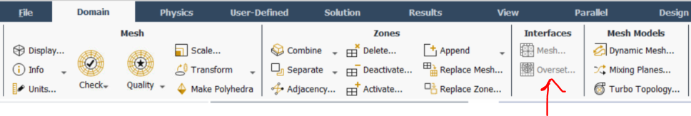 n
January 18, 2021 at 4:56 pm
n
January 18, 2021 at 4:56 pmDrAmine
Ansys EmployeeHave you done some exercises with Fluent tutorials? nJanuary 18, 2021 at 5:08 pmSubscriberHello DrAmine,nyes, I looked up several tutorials and searched online or in the help section.nKind regardsnJanuary 18, 2021 at 5:16 pmSubscriberArray Thanks for your answer!nCAR error:n--> Could this be due to the greyed-out Mesh Interface options and the fact that I would need to define the interface there? Any ideas on how I can fix that?.If you have two fluid zones check they're both fluid and one isn't solid due to the import.n--> In the Cell Zone Conditions, both zones are defined as fluids. So that should not be the problem.nKind regardsnJanuary 18, 2021 at 5:26 pmAnsys EmployeeAccording to your boundary names you have contact so actually you are a using a multi component mesh with some contact and hence you need to create interface connectionsnJanuary 18, 2021 at 6:48 pmYasserSelima
SubscriberI can see an outlet n your boundaries, but I can't see an outlet in your problem statement. Where is the outlet? Is it at the interface?nJanuary 19, 2021 at 8:38 amSubscriberArrayyes, I guess so. How can I define interfaces when Mesh Interface is greyed-out and not available?Arraythanks for your answer.nIn fact, in my problem, there is no outlet since I want to model the electrolyte filling and uptake process of a battery as a half model (-> symmetry) to investigate the time needed for the wetting.nThere is only an inlet for the electrolyte (-> liquid) for which I defined the pressure-inlet BC (inlet_void_volume). The liquid is then filled into an equivalent void volume (represented by a tank) and at some time soaked into the porous zone.nSo at the interface, I need to define a pressure-outlet BC but I now have two surfaces/edges:nthe so-named outlet_void_volume which is the left edge of the tanknthe so-named inlet_cell which is the right edge of the porous zonenI think those two BCs cause problems since they need to be just one BC. Is that right?nThank you in advance!nnJanuary 19, 2021 at 10:24 amAnsys EmployeeYou need to change the boundary conditions from WAll to Interfaces so that The Interface Panel is not greyed out. Perhaps you detect the contacts in pre-porcessing and provide already smart named selection like interface-site-1 interface-seite-2 etc..nNow you go the BC, change the the interface sides from wall to interfaces and then connect these sides in the interface panel!nnIf I look into your first picture:you actually have already interface sides (the names with trg and src at the end). Also the Mesh Interfaces does contain at least one defined interface connection. I have a feeling that you are breaking your case by reading a mesh into the case with different settings as you manipulated the mesh and Fluent keep tracks of that.nJanuary 19, 2021 at 10:25 amAnsys EmployeeYou have actually 4 pairs of interfaces and I recommend creating for each of the pair its own interface connections instead of putting all of them in one.nJanuary 19, 2021 at 2:38 pmSubscriberArray nYes that is right. As Dr. Amine mentioned, you need to change both of outlet_void_volume and inlet_cell into interface. nYou can not have something happening after the outlet or before the inlet. Always define the edge between zones into interface if you are expecting flow.nJanuary 19, 2021 at 3:55 pmSubscriberArray I did define both BCs as an interface. Then, I created the interface (Setup > Mesh Interfaces > Create/Edit Mesh Interfaces) selecting the two BCs outlet_void_volume and inlet_cell. Meanwhile, I had to change the names of the BCs to begin with an interface_xy, so that the Create/Edit Mesh Interfaces option was available.nSadly, the Mesh Check still fails and gives this warning:nError: interface zone 3 has two adjacent cell zones.nThe BC with ID 3 is the inlet_cell (right face of the porous zone).nAlso quite strange is, that the two BCs interface_void_volume (interface I just had defined) and outlet_void_volume were changed to be the upper piece of wall above the interface (s. screenshot).nAny ideas, how to solve this problem? My guess would be to change one of them to be a wall BC and to delete the other one, is that possible?n Note: zone-surface: cannot create surface from sliding interface zone. Creating empty surface."nSo my geometry is visualized a bit weird (screenshot). In a CFD Forum I found this explanation for the warning: simply means the boundaries of the non–conformal interfaces match exactly, such that there are no non–overlapping sections on either side of the interface (https://www.cfd-online.com/Forums/fluent/178102-cannot-create-surface-sliding-interface-zone-create-empty-surface.html#:~:text=Thankyou%20for%20looking%20into%20this%20problem.&text=The%20message%20%22Note%3A%20zone%E2%80%93,either%20side%20of%20the%20interface.)n
 Solution Animation Playback wouldn't work.nCalculation settings:ntime steps: 15,000ntime step size: 0.0001s.nReferring to these settings I also would like to ask how to take into account the following: I want the electrolyte to need 1s to enter through the pressure-inlet BC and then simulate a time of 2,7 hours since that's the expected time needed for the liquid to wet the porous zone in reality.n-> So there are two time horizons: one which is a few seconds and one which is 2,7 hours.nnSo here is a summary of my questions:nCan you confirm the explanation referring to the warning "Note: zone-surface: cannot create surface from sliding interface zone. Creating empty surface."?nDoes the Solution Animation Playback only work when the simulation converged?nWhat can I do about the „reverse flow on 4 phases on pressure-inlet" warning and could this be due to a false BC?nHow do I need to set the time steps and the time step size, in order to have two time horizons: one which is a few seconds (referring inlet) and one which is 2,7 hours (referring porous zone).nThank you very much in advance!nKind regards!n
January 25, 2021 at 1:53 pmSubscriber1- I am not sure about this message. I think you have no sliding interface. My understanding is that all your surfaces are not moving.n2 - Animation should work even if the solution does not converge.n3 -Your old geometry was better in the mesh size. Also as the inlet was higher than the interface, this would decrease the probability of back flow. Now you get back flow with any small eddies in the tank.n4 - Time step is function of the flow velocity V, and mesh size x. An estimate could be obtained by dividing V/x, then go below this number. Higher than this number, you will not capture transient details. But the overall solution can still be accurate. So, go for something lower in the first few seconds ... then increase it. Also you can use adaptive time step and let fluent optimise this for you.nnMy recommendation, go to the previous geometry and mesh. All you needed is define the boundary right. This would solve the back flow and hopefully the warning.nnJanuary 25, 2021 at 1:55 pmAdministratorHello,nHere are some answers.nThe explanation seems okay. To make sure, please identify which interface this warning is related to and understand how it was created. Are you creating all these interfaces from scratch? Or are you loading a different mesh into an existing case file? If you are doing this, I'd strongly recommend that you start from scratch.nNot necessarily. Solution Animation is independent of simulation convergence, as long as you set it right. To test this, you don't need to run your entire simulation. For debugging issues, please run the simulation for a few time-steps and check if the animation works.nRegarding this 'Pressure Inlet' boundary, I don't see an outlet condition in your computational domain. Without this, there is something missing from your model and you might always get some unphysical results. nYou could use a Fluent Expression for Multiphase. For t <= 1s, the volume fraction of electrolyte phase = 1. For t greater than 1 s, volume fraction = 0.nI hope this helps.nThanks.nKarthiknJanuary 25, 2021 at 3:07 pmSubscriberHello and thank you very much for the quick help!nMeanwhile, I refined the mesh a little bit.n
Solution Animation Playback wouldn't work.nCalculation settings:ntime steps: 15,000ntime step size: 0.0001s.nReferring to these settings I also would like to ask how to take into account the following: I want the electrolyte to need 1s to enter through the pressure-inlet BC and then simulate a time of 2,7 hours since that's the expected time needed for the liquid to wet the porous zone in reality.n-> So there are two time horizons: one which is a few seconds and one which is 2,7 hours.nnSo here is a summary of my questions:nCan you confirm the explanation referring to the warning "Note: zone-surface: cannot create surface from sliding interface zone. Creating empty surface."?nDoes the Solution Animation Playback only work when the simulation converged?nWhat can I do about the „reverse flow on 4 phases on pressure-inlet" warning and could this be due to a false BC?nHow do I need to set the time steps and the time step size, in order to have two time horizons: one which is a few seconds (referring inlet) and one which is 2,7 hours (referring porous zone).nThank you very much in advance!nKind regards!n
January 25, 2021 at 1:53 pmSubscriber1- I am not sure about this message. I think you have no sliding interface. My understanding is that all your surfaces are not moving.n2 - Animation should work even if the solution does not converge.n3 -Your old geometry was better in the mesh size. Also as the inlet was higher than the interface, this would decrease the probability of back flow. Now you get back flow with any small eddies in the tank.n4 - Time step is function of the flow velocity V, and mesh size x. An estimate could be obtained by dividing V/x, then go below this number. Higher than this number, you will not capture transient details. But the overall solution can still be accurate. So, go for something lower in the first few seconds ... then increase it. Also you can use adaptive time step and let fluent optimise this for you.nnMy recommendation, go to the previous geometry and mesh. All you needed is define the boundary right. This would solve the back flow and hopefully the warning.nnJanuary 25, 2021 at 1:55 pmAdministratorHello,nHere are some answers.nThe explanation seems okay. To make sure, please identify which interface this warning is related to and understand how it was created. Are you creating all these interfaces from scratch? Or are you loading a different mesh into an existing case file? If you are doing this, I'd strongly recommend that you start from scratch.nNot necessarily. Solution Animation is independent of simulation convergence, as long as you set it right. To test this, you don't need to run your entire simulation. For debugging issues, please run the simulation for a few time-steps and check if the animation works.nRegarding this 'Pressure Inlet' boundary, I don't see an outlet condition in your computational domain. Without this, there is something missing from your model and you might always get some unphysical results. nYou could use a Fluent Expression for Multiphase. For t <= 1s, the volume fraction of electrolyte phase = 1. For t greater than 1 s, volume fraction = 0.nI hope this helps.nThanks.nKarthiknJanuary 25, 2021 at 3:07 pmSubscriberHello and thank you very much for the quick help!nMeanwhile, I refined the mesh a little bit.n January 25, 2021 at 4:01 pmSubscriberFor the animation, when recording, create the frame you want to record ...then in the solution, go to create animation and select this frame and the file type HSF. Then in the results, you can create video from this animation. nJanuary 27, 2021 at 6:17 pmSubscriberArray thanks for your tips! I tried to implement them!nI changed the geometry so that the inlet is now a channel, starting far above (screenshot).n
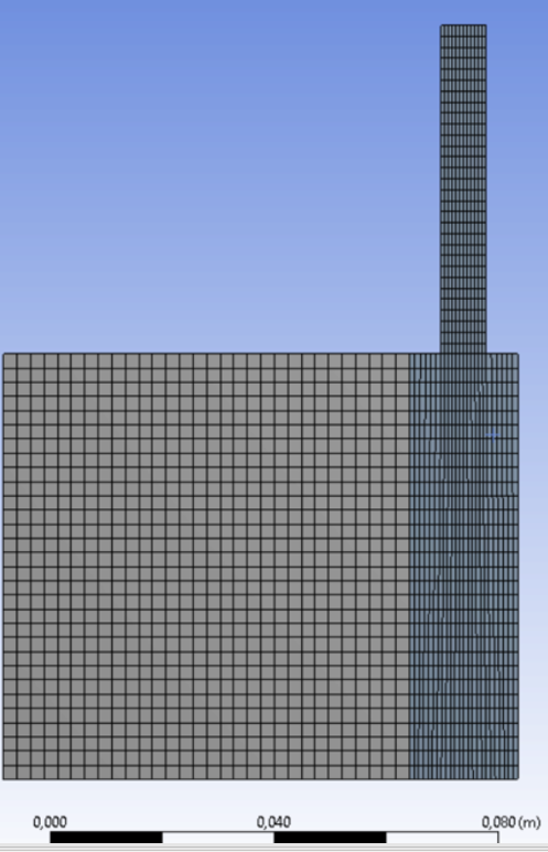 Also, I decreased the Under-Relaxation-Factors and increased the number of iterations per time step from 50 to 60.nWhen I first tried to simulate it with your suggested k-omega SST turbulence model it diverged. Interestingly, it worked with Reynolds Stress model. nSo now I was trying to play around with the number of time steps and time step size, therefore getting different convergence profiles. I changed the Absolute criteria of energy, momentum, etc. to 1e-06. Maybe this is too small?nAre those profiles showing convergence? For the upper curve, I set 100 time steps & 0.01s.nn
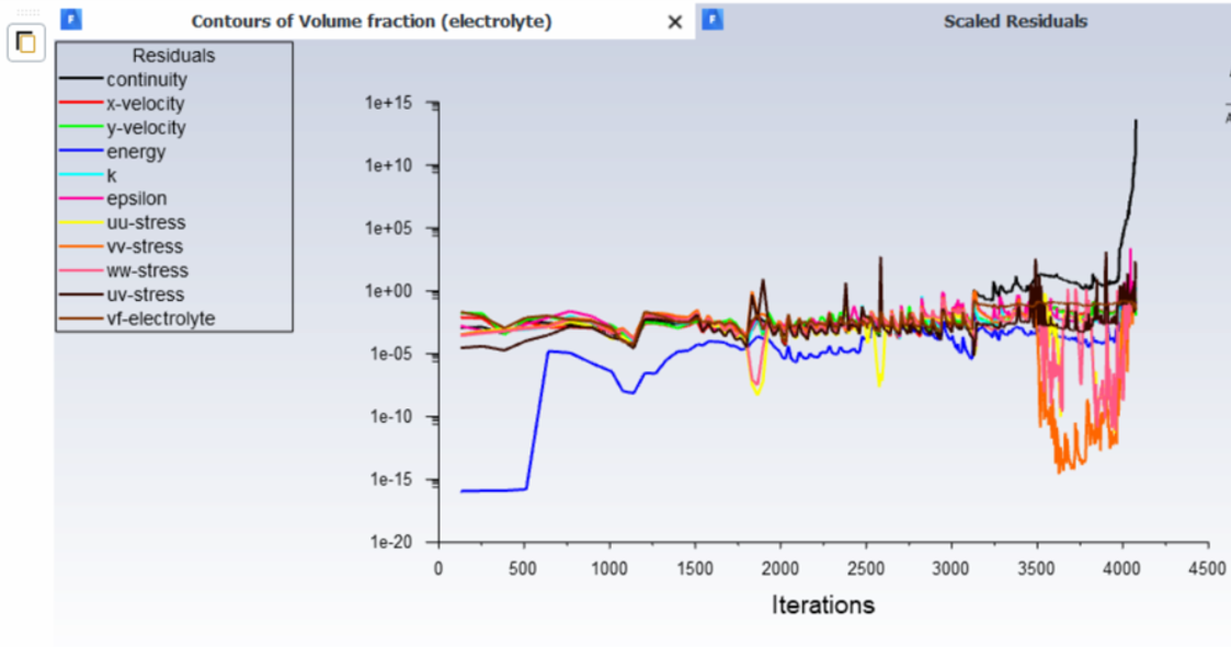 n
n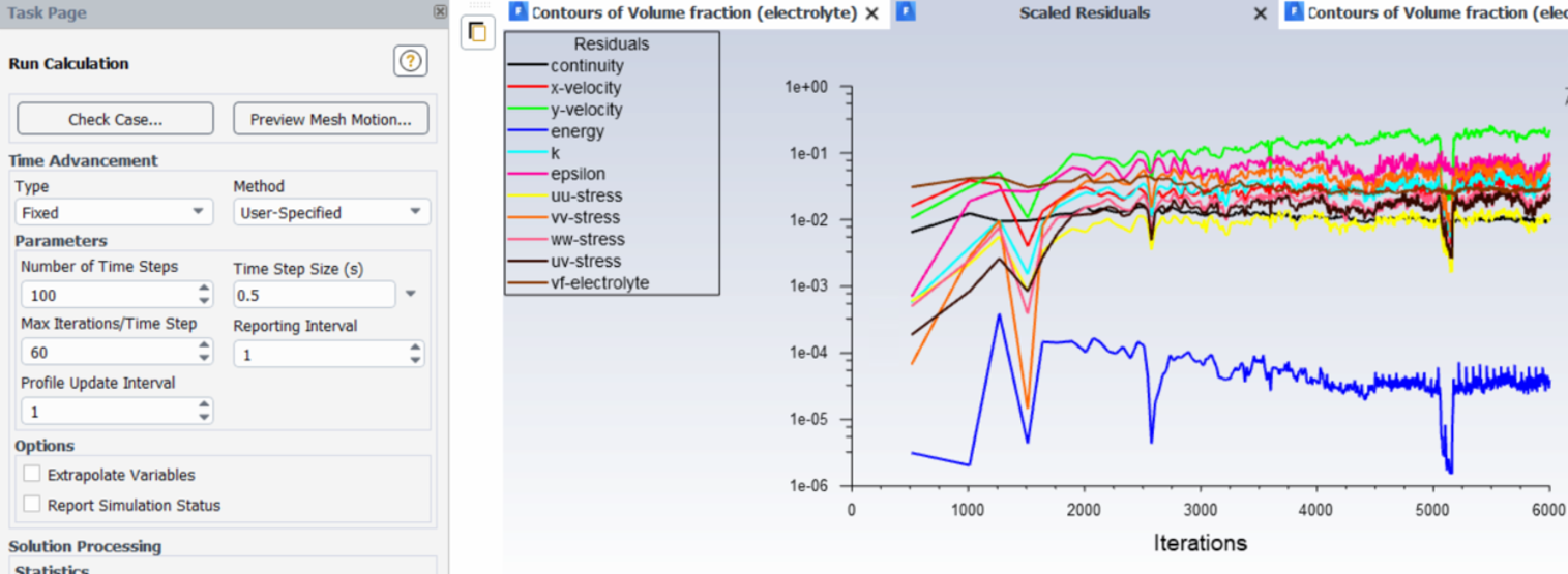 nThe main goal is as follows:nI want a defined amount of liquid (x ml) to need a few seconds to enter through the pressure-inlet.nI want to simulate a time of a few hours (2-3 h) since that's the expected time in reality.nIdeally, I want to fill in liquid twice, such that I fill in for example half of the desired amount at t=0 and the other amount at t=1?nIs there a way to achieve this? Array You already mentioned some sort of possibility?.Thank you in advance!
January 28, 2021 at 1:08 pmSubscriberGetting different solutions for different time steps means the solution is not converged deeply ... This would come fromn1) Mesh size is too large to capture physicsn2) Time step is too large to capture transient detailsn3) Not enough number of iterations for the solution to converge every time step.nI would look into them by order ... First I will decrease the time step to a very low number. Let's say 1e-05 and make convergence criteria very low residuals .. say 1e-06 as you selected. Then start by a coarse and solve for 200 -- 300 time steps. Then refine the mesh, and solve again and compare the results. Keep refining until you find similar solution .. now this is my mesh.nMove to the time step. increase it slightly and compare the solution. until you find it affects the solution.nFinally increase the residuals criteria and see what is the highest number that does not affect the solution.nOnce you make a decision on the above three, you can change parameters and play with the model and compare to experiments. Parameters as turbulence model .. Use second order equations instead of 1 and so on until you get the best comparison with experiments. Now your model is validated and working ... It is time to answer I want to Questions ...n1) you can have inlet flow at the beginning for first few seconds and control the flown2)If you need to capture details in the 2-3 hours, you have to continue on the same criteria ... If the details are not important, you can increase the convergence criteria (residuals) or decrease the number of iterations. n3) you can patch any amount you want nJanuary 28, 2021 at 2:16 pmSubscriberArraythank you so much for the detailed explanations, those helped a lot. I will implement them!nnReferring to the last questions, I have still some doubts about how to achieve my goals:n1: you can have inlet flow at the beginning for first few seconds and control the flow -> How can I control the flow? While doing the initialization step?n3: you can patch any amount you want -> Do you mean the Patch function in the initialization step? How exactly is it possible to define two initializations?.Thank you very much! Kind regards!nJanuary 28, 2021 at 3:25 pmSubscriberyou have inlet boundary condition, change the velocity to have the required flow rate.nAfter initialising the solution, you can patch the initial state of the system. Like patch N2 in the porous zone. nViewing 28 reply threads
nThe main goal is as follows:nI want a defined amount of liquid (x ml) to need a few seconds to enter through the pressure-inlet.nI want to simulate a time of a few hours (2-3 h) since that's the expected time in reality.nIdeally, I want to fill in liquid twice, such that I fill in for example half of the desired amount at t=0 and the other amount at t=1?nIs there a way to achieve this? Array You already mentioned some sort of possibility?.Thank you in advance!
January 28, 2021 at 1:08 pmSubscriberGetting different solutions for different time steps means the solution is not converged deeply ... This would come fromn1) Mesh size is too large to capture physicsn2) Time step is too large to capture transient detailsn3) Not enough number of iterations for the solution to converge every time step.nI would look into them by order ... First I will decrease the time step to a very low number. Let's say 1e-05 and make convergence criteria very low residuals .. say 1e-06 as you selected. Then start by a coarse and solve for 200 -- 300 time steps. Then refine the mesh, and solve again and compare the results. Keep refining until you find similar solution .. now this is my mesh.nMove to the time step. increase it slightly and compare the solution. until you find it affects the solution.nFinally increase the residuals criteria and see what is the highest number that does not affect the solution.nOnce you make a decision on the above three, you can change parameters and play with the model and compare to experiments. Parameters as turbulence model .. Use second order equations instead of 1 and so on until you get the best comparison with experiments. Now your model is validated and working ... It is time to answer I want to Questions ...n1) you can have inlet flow at the beginning for first few seconds and control the flown2)If you need to capture details in the 2-3 hours, you have to continue on the same criteria ... If the details are not important, you can increase the convergence criteria (residuals) or decrease the number of iterations. n3) you can patch any amount you want nJanuary 28, 2021 at 2:16 pmSubscriberArraythank you so much for the detailed explanations, those helped a lot. I will implement them!nnReferring to the last questions, I have still some doubts about how to achieve my goals:n1: you can have inlet flow at the beginning for first few seconds and control the flow -> How can I control the flow? While doing the initialization step?n3: you can patch any amount you want -> Do you mean the Patch function in the initialization step? How exactly is it possible to define two initializations?.Thank you very much! Kind regards!nJanuary 28, 2021 at 3:25 pmSubscriberyou have inlet boundary condition, change the velocity to have the required flow rate.nAfter initialising the solution, you can patch the initial state of the system. Like patch N2 in the porous zone. nViewing 28 reply threads- The topic ‘URGENT: Cannot patch region for phase 1 (N2) of my two-phase simulation with porous media’ is closed to new replies.
Innovation Space Trending discussions
 Top Contributors
-
peteroznewman
 6520
6520 -
scabo
 1906
1906 -
Dennis Chen
 1463
1463 -
javat33489
 1310
1310 -
Shyam Prasad V Atri
1022
Top Rated Tags
© 2026 Copyright ANSYS, Inc. All rights reserved.
Ansys does not support the usage of unauthorized Ansys software. Please visit www.ansys.com to obtain an official distribution.
-


Please Login to Report Topic
Please Login to Share Feed