

TAGGED: static-structural
-
-
January 11, 2021 at 10:48 am
raviteja111
SubscriberI have done simulation in Ansys fluent. At the initial position, turbine blades are at 0 degrees, at this position I have simulated the forces acting on the blades in the z-direction. I got a familiar result.
but when I change the blade angle to 30 degrees. forces are getting in minus(-) value.
can anyone explain what I have did a mistake?
January 11, 2021 at 10:51 amDrAmine
Ansys Employee1/Insert and do not attach picturesn2/Aslo how are you defining the force report: you probably providing the direction to get the forces. nJanuary 11, 2021 at 10:56 amSubscriber1/Insert and do not attach pictures2/Aslo how are you defining the force report: you probably providing the direction to get the forces./forum/discussion/comment/102616#Comment_102616
I have inserted the images. have a look at them?.January 11, 2021 at 11:36 amRob
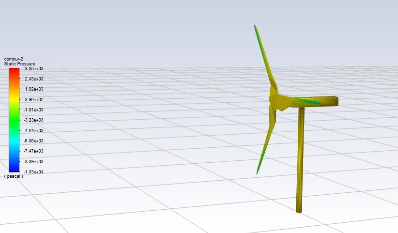
Forum ModeratorThat looks like the blades are pitched forwards rather than twisted?nJanuary 11, 2021 at 12:01 pmSubscribernThat looks like the blades are pitched forwards rather than twisted?/forum/discussion/comment/102621#Comment_102621
yes blades are pitched and at the same time they regulate. at initial condition at 0 degrees I got force about 2500N but in the second case when I pitched the angle I got -273N.nnJanuary 11, 2021 at 1:24 pmForum ModeratorWhat force vector did you use? Ie was it the right one?.January 11, 2021 at 8:19 pmYasserSelima
SubscriberYou are forcing the blades to run by a specific rpm. What if the lift force on the blades is not enough to apply this moment? You get negative lift ... and negative thrust. In other words, may be it is working as a blower instead of a turbine.January 12, 2021 at 8:04 amAnsys EmployeeMoreover can you review the angular speed and especially the the rotational axis direction?nJanuary 13, 2021 at 2:01 pmSubscriberMoreover can you review the angular speed and especially the the rotational axis direction?/forum/discussion/comment/102752#Comment_102752
257.54 rpm at rotational axis.nJanuary 13, 2021 at 2:05 pmSubscriberWhat force vector did you use? Ie was it the right one?/forum/discussion/comment/102639#Comment_102639
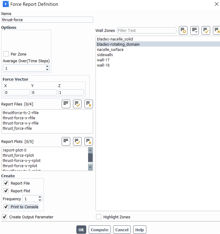 in Z-directionn
 This one rotating domain.n
January 13, 2021 at 6:03 pmAnsys EmployeeI am not sure because you have all right . Only the way the blades are twisted is not what I used to know. Are you sure about angular speed: might be creating negative lift. Have you till convergence of thrust monitor.nJanuary 14, 2021 at 11:03 amSubscriber
This one rotating domain.n
January 13, 2021 at 6:03 pmAnsys EmployeeI am not sure because you have all right . Only the way the blades are twisted is not what I used to know. Are you sure about angular speed: might be creating negative lift. Have you till convergence of thrust monitor.nJanuary 14, 2021 at 11:03 amSubscriberYou are forcing the blades to run by a specific rpm. What if the lift force on the blades is not enough to apply this moment? You get negative lift ... and negative thrust. In other words, may be it is working as a blower instead of a turbine./forum/discussion/comment/102715#Comment_102715
In the real world, we have some forces acting on the blades. How can we calculate those forces in a simulation? Is there any possibility to calculate the forces at that position? nJanuary 14, 2021 at 4:16 pmSubscriberYes, forces and moment. nThere is a function called Compute_Force_And_Moment defined in the wall header file. Unfortunately it is not mentioned in fluent documentation. nIt would work in your case by calculating the moment around your turbine axis. nJanuary 14, 2021 at 4:17 pmSubscriberI will put it here once I am on my desk and I will let you know how to use. nJanuary 14, 2021 at 4:19 pmSubscriberAre you using CG motion?nJanuary 14, 2021 at 4:53 pmSubscriberAre you using CG motion?/forum/discussion/comment/103080#Comment_103080
No, I think. where should I mention it?.January 14, 2021 at 5:23 pmSubscriberOk, here is the idea but it will need some work from younInstead of rotating your turbine with a constant rpm, use a user defined function to rotate it with the fluid forces. You can even apply a resisting torque and see how the speed will change. You need to write a user defined function. Calculate the moment on the turbine and rotate it according to the governing equation: ndelta_omga / timestep * Moment_of_Inertia = sum_of_TorquennThe user defined function will be something like this n#include udf.hn#include f_wall.hn#include dynamesh_tools.hndouble old_omega = 0;nDEFINE_CG_MOTION (turbine, dt, vel, omega, time, dtime)n{n double I = ---; / Moment of inertia n double T_load = 0; / You can add the resistance load herentif (!Data_Valid_P())n ttreturn;ntNV_S (vel, =, 0.0);ntNV_S (omega, =, 0.0);ntdouble moment [ND_ND], cg[ND_ND], force [ND_ND];ntCompute_Force_And_Moment(d, t, cg, force, moment, TRUE);n tdouble Torque = moment[2]; n double delta_omega = dtime*(Torque - T_load)/I;ntold_omga += delta_omega;n omega[2]=old_omega;n t#if RP_HOSTnttMessage ( old_omega = %f, Moment = %f, old_omega, Torque); nt#endifnnthe compute Force and moment function will return the values of moment nCompile this function and then go to dynamic mesh and select your turbine and rigid body motion and udf ... and good luck!nJanuary 14, 2021 at 5:39 pmSubscriberAnother way to go around the UDF is to use expression for the rpm nHere you need to define an expression for the thrust forcenThen another conditional expression =1 if the thrust is positive and =-1 if the thrust is negative .. let's call domeganand a third expression of the turbine boundary angular velocity .. let's call it old_omeganThen make your rpm old_omega +domeganhere fluent will increase your rpm by one every iteration until it has zero thrustnJanuary 14, 2021 at 5:50 pmSubscribernJanuary 15, 2021 at 4:07 pmSubscriberplease let me know if it worked.nJanuary 16, 2021 at 8:08 pmSubscriberOk, here is the idea but it will need some work from youInstead of rotating your turbine with a constant rpm, use a user defined function to rotate it with the fluid forces. You can even apply a resisting torque and see how the speed will change. You need to write a user defined function. Calculate the moment on the turbine and rotate it according to the governing equation: delta_omga / timestep * Moment_of_Inertia = sum_of_TorqueThe user defined function will be something like this #include "udf.h"#include "f_wall.h"#include "dynamesh_tools.h"double old_omega = 0;DEFINE_CG_MOTION (turbine, dt, vel, omega, time, dtime){ double I = ---; // Moment of inertia double T_load = 0; // You can add the resistance load heretif (!Data_Valid_P()) ttreturn;tNV_S (vel, =, 0.0);tNV_S (omega, =, 0.0);tdouble moment [ND_ND], cg[ND_ND], force [ND_ND];tCompute_Force_And_Moment(d, t, cg, force, moment, TRUE); tdouble Torque = moment[2]; double delta_omega = dtime*(Torque - T_load)/I;told_omga += delta_omega; omega[2]=old_omega; t#if RP_HOSTttMessage ("
Thanks for the time you spent on my work. nI tried to compile this code in visual studio, it's showing 12 errors. I am so bad at c program. can you please suggest a way? n
old_omega = %f, Moment = %f", old_omega, Torque); t#endif}the compute Force and moment function will return the values of moment Compile this function and then go to dynamic mesh and select your turbine and rigid body motion and udf ... and good luck!/forum/discussion/comment/103091#Comment_103091January 16, 2021 at 8:19 pmSubscribercompile using the built in compiler. in fluent select user defined tab, then functions, compile .. check the built in compiler box. and built. probably you will get different error. Visual studio doesn't know the header files in fluent .. so it will come with more errors. nViewing 21 reply threads- The topic ‘Forces acting on wind turbine blade’ is closed to new replies.
Innovation Space Trending discussions
 Top Contributors
-
peteroznewman
 6515
6515 -
scabo
 1906
1906 -
Dennis Chen
 1463
1463 -
javat33489
 1309
1309 -
Shyam Prasad V Atri
1022
Top Rated Tags
© 2026 Copyright ANSYS, Inc. All rights reserved.
Ansys does not support the usage of unauthorized Ansys software. Please visit www.ansys.com to obtain an official distribution.
-


 You are navigating away from the AIS Discovery experience